
Optical time domain reflectometer test method and optical time domain reflectometer

An optical time domain reflectometer and a testing method technology, applied in the field of communication, can solve the problem that the measurement range cannot be adjusted according to the on-site situation, and achieve the effects of solving the fixed measurement range, increasing the optical power, and expanding the measurement range

Active Publication Date: 2021-11-02
CHINA MOBILE GRP HENAN CO LTD
View PDF12 Cites 0 Cited by
  • Summary
  • Abstract
  • Description
  • Claims
  • Application Information

AI Technical Summary

Problems solved by technology

However, since the measurement range of the OTDR equipment in the prior art has been fixed after leaving the factory, the measurement range cannot be adjusted according to the on-site conditions, and if the measurement range is exceeded, the OTDR equipment with other measurement ranges can only be replaced.

Method used


Image

  • Optical time domain reflectometer test method and optical time domain reflectometer
  • Optical time domain reflectometer test method and optical time domain reflectometer
  • Optical time domain reflectometer test method and optical time domain reflectometer

Examples


Embodiment Construction

[0013] In order to make the purpose, technical solutions and advantages of the embodiments of the present invention clearer, the technical solutions in the embodiments of the present invention will be clearly described below in conjunction with the accompanying drawings in the embodiments of the present invention. Obviously, the described embodiments are the Some, but not all, embodiments are invented. Based on the embodiments of the present invention, all other embodiments obtained by persons of ordinary skill in the art without making creative efforts belong to the protection scope of the present invention.

[0014] For the optical time domain reflectometer, a chaotic correlation optical time domain reflectometer (COTDR) has been studied in the prior art. By performing cross-correlation calculations on the reference light and the reflected light at the fault location, the fault with a spatial resolution of 6cm is realized. Positioning improves the test distance and test accu...


PUM


Abstract

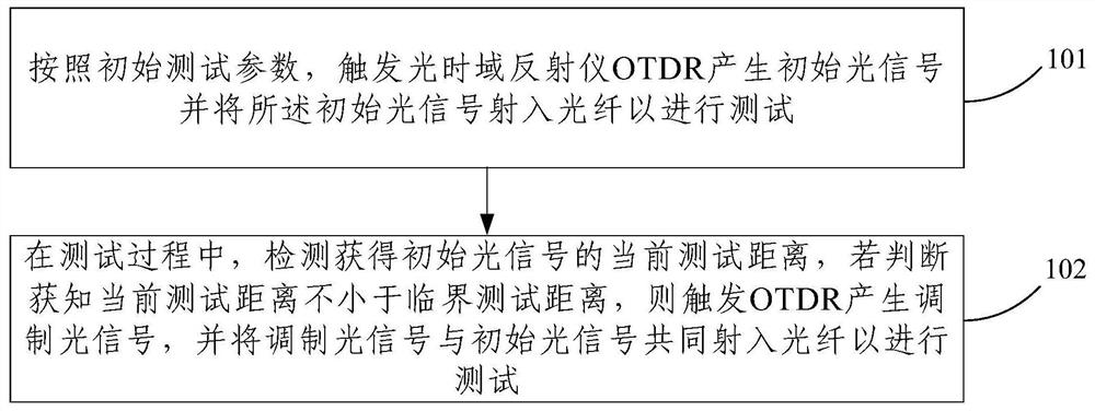
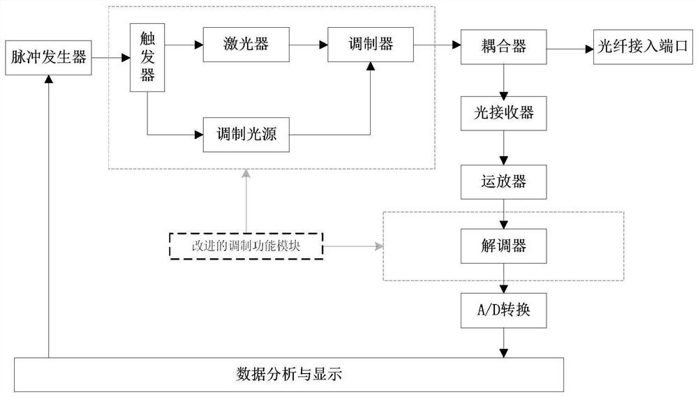
An embodiment of the present invention provides an optical time domain reflectometer test method and an optical time domain reflectometer. The method includes: triggering an optical time domain reflectometer OTDR to generate an initial optical signal according to initial test parameters, and injecting the initial optical signal into an optical fiber During the test, the current test distance obtained by detecting the initial optical signal is detected, and if it is judged that the current test distance is not less than the critical test distance, the OTDR is triggered to generate a modulated optical signal, and the modulated optical signal and the initial optical signal are emitted together. into the fiber for testing. The embodiments of the present invention increase the optical power of the test input end by triggering the OTDR to generate a modulated optical signal when the current test distance is not less than the critical test distance, so the measurement range of the OTDR can be expanded, thereby solving the problem of the fixed measurement range of the OTDR and the noise of the measurement track flooding problem.

Description

technical field [0001] Embodiments of the present invention relate to the technical field of communications, and more specifically, to an optical time domain reflectometer test method and an optical time domain reflectometer. Background technique [0002] OTDR is an Optical Time Domain Reflectometer (OpticaL Time Domain RefLectometer), which is mainly used in the field of optical fiber communication and has a high frequency of use. In practical application, OTDR is mainly used to test the optical fiber, and according to the different waveforms displayed on the graphical interface, the faults in the optical path can be quickly and accurately judged and located. The principle is that under the control of the precise clock circuit, the maintainer sets the parameters according to the actual test scene, and sends an optical pulse signal to the optical port, and then the OTDR continuously receives the optical signal reflected from the optical fiber from the optical port at a certa...

Claims


Application Information

Patent Timeline
Patent Type & Authority Patents(China)
IPC IPC(8): H04B10/071
CPCH04B10/071
Inventor 王云谦刘法平周外喜段新明唐志文马慧芳熊燕
Owner CHINA MOBILE GRP HENAN CO LTD
Learn More