
Node optimal deployment method suitable for wireless positionable sensor network

A sensor node, positioning sensing technology, applied in wireless communication, network topology, network planning and other directions, can solve the problems of building energy transmission model, energy waste, not considering the impact of dynamic changes in charging problems, etc.

Active Publication Date: 2020-05-15
广东冠兴科技发展有限公司
View PDF8 Cites 4 Cited by
  • Summary
  • Abstract
  • Description
  • Claims
  • Application Information

AI Technical Summary

Problems solved by technology

When the charger charges the sensor node, the microwave energy transmitted in the space will attenuate with the increase of the distance. When no sensor node receives the energy, there will be energy waste. Therefore, the charger and the sensor node The location deployment has a great influence on the node resource planning problem
However, the existing wireless charging research usually fixes the position of the sensor node, then deploys the mobile charging device in the network, and uses the path optimization algorithm to plan its optimal route, without considering the dynamic change of the sensor node position deployment. Impact on Charging Issues
At the same time, in the existing research on the energy transfer model, the sensor node is usually based on an adaptive distributed algorithm, and communicates with the surrounding common nodes by adjusting its own optimal data transmission rate, link flow, and routing path, without antenna-based Radiation features to build energy transfer models

Method used


Image

  • Node optimal deployment method suitable for wireless positionable sensor network
  • Node optimal deployment method suitable for wireless positionable sensor network
  • Node optimal deployment method suitable for wireless positionable sensor network

Examples


Embodiment Construction

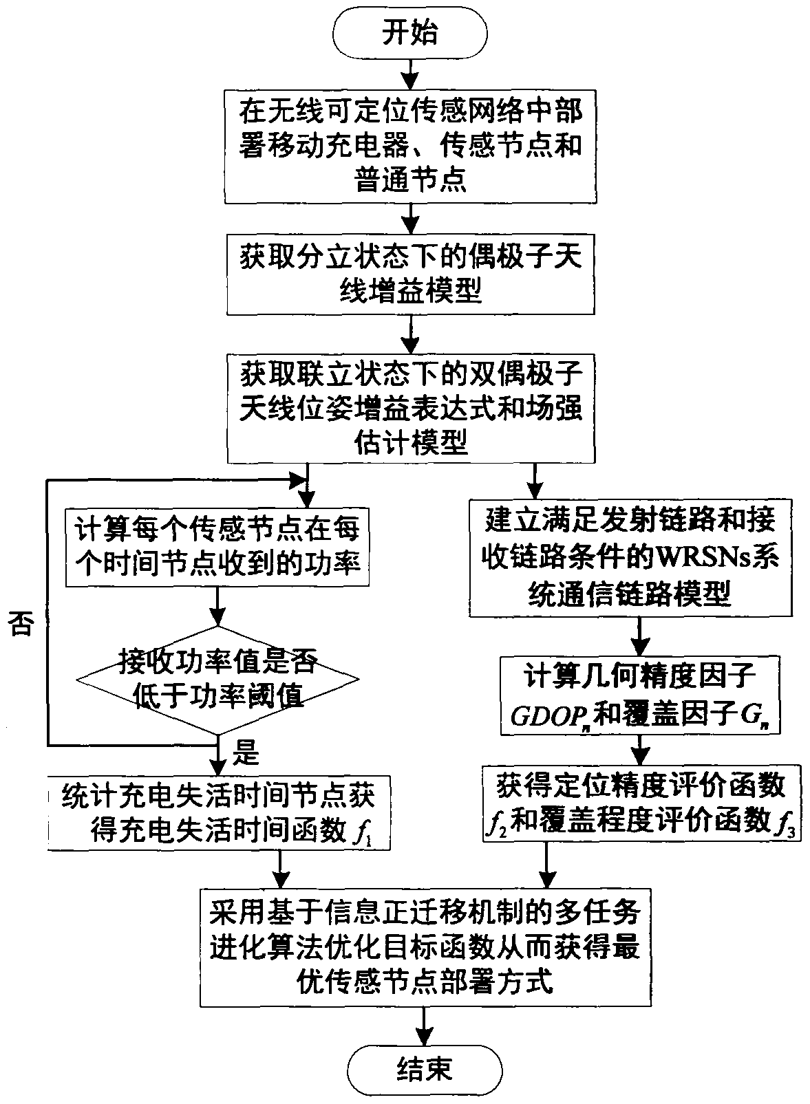
[0021] First of all, build a wireless positionable sensor network system based on chargers, sensor nodes, common nodes and service stations, with the goal of reducing the charging inactivation time of the system, improving the positioning accuracy and coverage of the system, and based on the popularization of the market To a certain extent, the dipole antenna is selected as the charger, sensor node and common node antenna, and the gain estimation model of the dipole antenna in the discrete state is obtained according to the classical electromagnetic field theory.

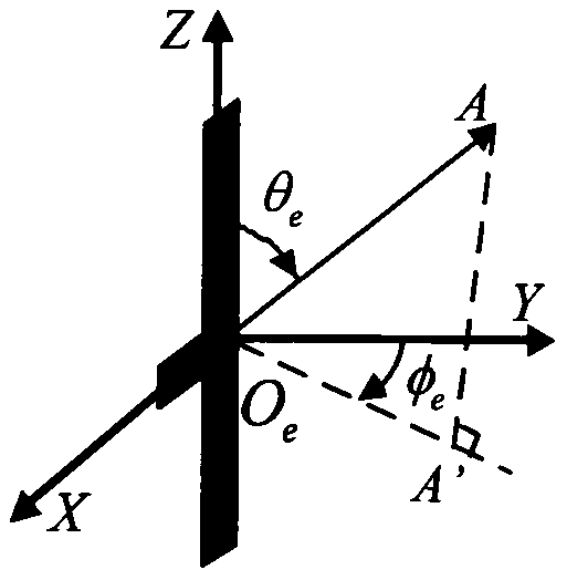
[0022] Such as figure 2 Shown is a schematic diagram of the coordinate system of the dipole tag antenna. Assuming that the antenna size satisfies the "half-wavelength" condition, its gain estimation model can be described as

[0023]

[0024] Among them, O e Constitute a ray vector with a point A in space θ e is the Z-axis to ray vector to the angle, φ e is the ray vector After projecting on the XOY pla...


PUM


Abstract

The invention belongs to the field of wireless sensor networks, and relates to a node optimal deployment method suitable for a wireless positionable sensor network. The method aims at processing optimal deployment of wireless positionable sensor network nodes, and comprises the following steps: acquiring a sensor node antenna gain estimation model in a discrete state; constructing a double-dipoleantenna radiation gain model and a field intensity estimation model in a simultaneous state; obtaining an optimization objective function through communication among a mobile charger, a sensing node and a common node; and optimizing a target function by adopting a multitask evolutionary algorithm based on an information positive migration mechanism to obtain an optimal deployment mode of the sensing nodes. The method has the characteristics that the energy utilization rate of the charger is effectively improved, the charging inactivation time is shortened, and meanwhile, the requirements of high-precision positioning and large-range coverage of the whole system are met.

Description

technical field [0001] The invention belongs to the field of wireless sensor networks, and relates to a node optimization deployment method suitable for wireless positionable sensor networks. Background technique [0002] Thanks to the rapid development of wireless communication technology, remote sensing technology, computer technology and microelectronics manufacturing technology, Wireless Rechargeable Sensor Networks (WRSNs) have emerged and been widely used. Different from traditional battery-powered nodes, sensor nodes in wireless rechargeable sensor networks collect energy through radio frequency signals and other energy sources. The charging process is less affected by changes in the surrounding environment, which can effectively extend the normal working life of the network. In WRSNs, the deployment method of sensing nodes is an important factor affecting charging time, charging efficiency and positioning accuracy of ordinary nodes. The optimal deployment of nodes ba...

Claims


Application Information

Patent Timeline
IPC IPC(8): H04W16/20H04W16/22H04W84/18H04B17/391H04B17/327
CPCH04W16/20H04W16/225H04W84/18H04B17/391H04B17/327Y02D30/70
Inventor 史伟光王山川王薇
Owner 广东冠兴科技发展有限公司
Learn More