
Rolling deoiling device

A pair of oil-absorbing roll technology, applied in the field of strip rolling, can solve problems such as abnormal operation, emulsion spots, product surface defects, etc., to ensure long-term stable operation, improve efficiency and effect, and reasonable structural design Effect

Pending Publication Date: 2020-05-19
MAANSHAN IRON & STEEL CO LTD
View PDF0 Cites 1 Cited by
  • Summary
  • Abstract
  • Description
  • Claims
  • Application Information

AI Technical Summary

Problems solved by technology

[0002] In the steel rolling industry, strips often need to be rolled through a rolling mill. However, a large amount of emulsion is used for cooling and lubrication during the rolling process, which results in a large amount of residual emulsion on the surface of the strip after rolling. These emulsions can further form emulsion spots, leading to product surface defects
[0003] Most of the existing degreasing devices simply set up a pair of oil-absorbing rollers. The two ends of the oil-absorbing rollers are respectively arranged on the archway. It is not synchronized with the operation up and down; because the rolling speed is very high, the bent and deformed oil absorption roller will vibrate violently when it rotates with the strip steel, so it cannot operate normally and absorb the residual emulsion
At present, there is a lack of a kind of equipment that can quickly and stably remove the residual emulsion on the surface of the strip steel during the production process, which needs to be solved urgently

Method used


Image

  • Rolling deoiling device
  • Rolling deoiling device
  • Rolling deoiling device

Examples


specific example

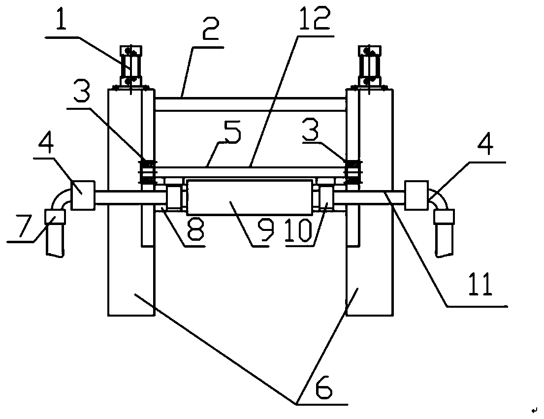
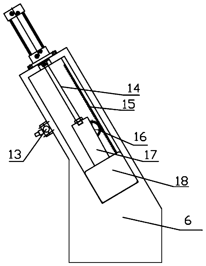
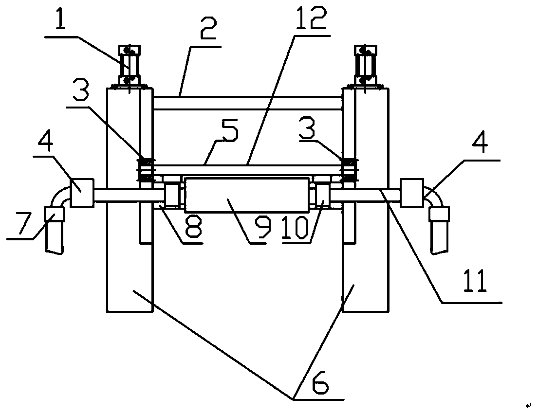
[0034] The device has two arches 6, on which other equipment components are installed and fixed, the core of which is the oil suction roller 9, which is fixed on the bottom plate 8 through the bearing seats 10 on both sides, and the bottom plate 8 passes through the sliding seats on both sides 18 is constrained in the chute on the archway 6, and the piston rod 14 of the lifting cylinder 1 installed on the archway is connected with the bottom plate slide seat 18 of the oil-suction roller through the connecting head 17; thus, under the promotion of the lifting cylinder, the oil-suction roller 9 With the sliding seat 18 to move up and down, at the same time, the sliding seats 18 on both sides are equipped with a synchronous gear 3, and the two synchronous gears 3 are connected by the synchronous connecting rod 5, and at the same time, synchronous racks are installed on both sides of the archway 6 15. When the lifting cylinder 1 pushes the sliding seat 18 to move up and down, due t...


PUM


Abstract

The invention discloses a rolling deoiling device. The rolling deoiling device comprises a pair of stands, a deoiling mechanism and lifting cylinders, wherein the stands are used for bearing and installing the deoiling mechanism and the lifting cylinders; the deoiling mechanism comprises an oil suction roller, a pair of bearing structures, bottom plates and slide bases, the end portions of the oilsuction roller are arranged on the bottom plates on the corresponding sides through the bearing structures, and the bottom plates are arranged on the slide bases on the corresponding sides; the lifting cylinders are fixed to the stands, and piston rods of the lifting cylinders are connected with the slide bases. By means of the rolling deoiling device, the problems that an oil suction roller is deformed and bent, and the ascending and descending motions of the two sides of the oil suction roller are non-synchronous, it is effectively ensured that the oil suction roller stably runs for a longperiod, and the efficiency and effect of adsorbing remaining lubricating oil / emulsions are improved. Through the internal negative-pressure adsorption, the oil suction roller can further improve the deoiling effect.

Description

technical field [0001] The invention relates to the technical field of strip rolling, in particular to a rolling degreasing device. Background technique [0002] In the steel rolling industry, strips often need to be rolled through a rolling mill. However, a large amount of emulsion is used for cooling and lubrication during the rolling process, which results in a large amount of residual emulsion on the surface of the strip after rolling. These emulsions can further form emulsion spots, leading to product surface defects. [0003] Most of the existing degreasing devices simply set up a pair of oil-absorbing rollers. The two ends of the oil-absorbing rollers are respectively arranged on the archway. It is asynchronous with the operation up and down movement; due to the very high rolling speed, the bent and deformed oil absorption roller will vibrate violently when it rotates with the strip steel, so it cannot operate normally and absorb the residual emulsion. At present, t...

Claims


Application Information

Patent Timeline
Patent Type & Authority Applications(China)
IPC IPC(8): B21B45/02
CPCB21B45/0281B21B45/0284
Inventor 付军发严开龙叶明成胡柯杜克飞林攀庞建韩恒恒
Owner MAANSHAN IRON & STEEL CO LTD
Learn More