A CNC machine tool

A technology of CNC machine tools and racks, applied in metal processing machinery parts, metal processing equipment, maintenance and safety accessories, etc., can solve the problems of reducing the speed of cutting fluid passing, reducing the quality of workpiece processing, affecting the reuse of cutting fluid, etc. Achieve the effect of speeding up heat dissipation, speeding up the drop of oil temperature and improving quality

Active Publication Date: 2021-01-12
浙江恒大数控装备有限公司
View PDF1 Cites 0 Cited by
  • Summary
  • Abstract
  • Description
  • Claims
  • Application Information

AI Technical Summary

Problems solved by technology

[0004] The above-mentioned technical solution has the following defects: the metal filter is used to filter the iron filings in the cutting fluid, and when the mesh is small, it is easy to be blocked by the iron filings, reducing the passing speed of the cutting fluid, so that the cutting fluid returns to the cutting fluid recovery pool The medium is slower, which affects the subsequent reuse of cutting fluid; the larger the mesh size, the smaller the iron filings will leak, causing the cutting fluid to damage the workpiece when it is sprayed on the workpiece, reducing the processing quality of the workpiece

Method used


Image

  • A CNC machine tool
  • A CNC machine tool
  • A CNC machine tool

Examples


Embodiment Construction

[0043] The present invention will be described in further detail below in conjunction with the accompanying drawings.

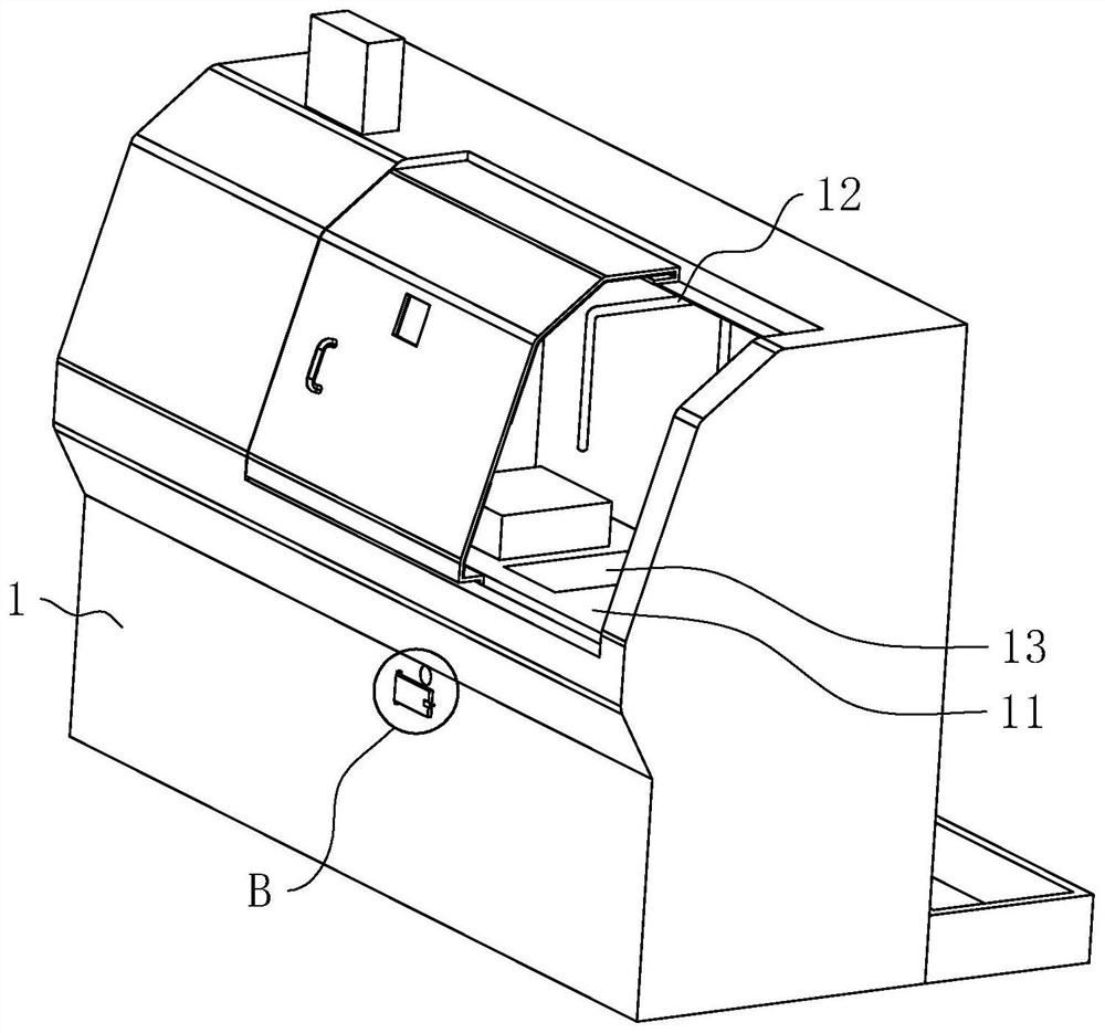
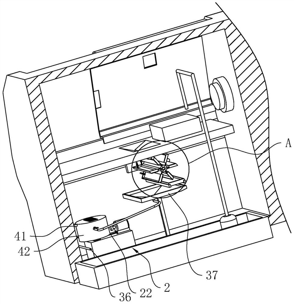
[0044] refer to figure 1 and figure 2 , a numerical control machine tool, comprising a frame 1, a workbench 11 and a cooling pipe 12 are fixedly arranged on the frame 1, a hydraulic station 2 is arranged in the frame 1 and below the workbench 11, and a liquid receiving bucket is arranged on the workbench 11 13. A collection bucket 37 is fixedly installed on the frame 1 below the liquid tray 32. The bottom of the collection bucket 37 is connected with a drain pipe 38 leading to the outside of the frame 1. After the cooling pipe 12 sprays the cutting fluid, it passes through the liquid bucket 13. Fall in the collection bucket 37, then be discharged outside the frame 1 from the collection bucket 37.

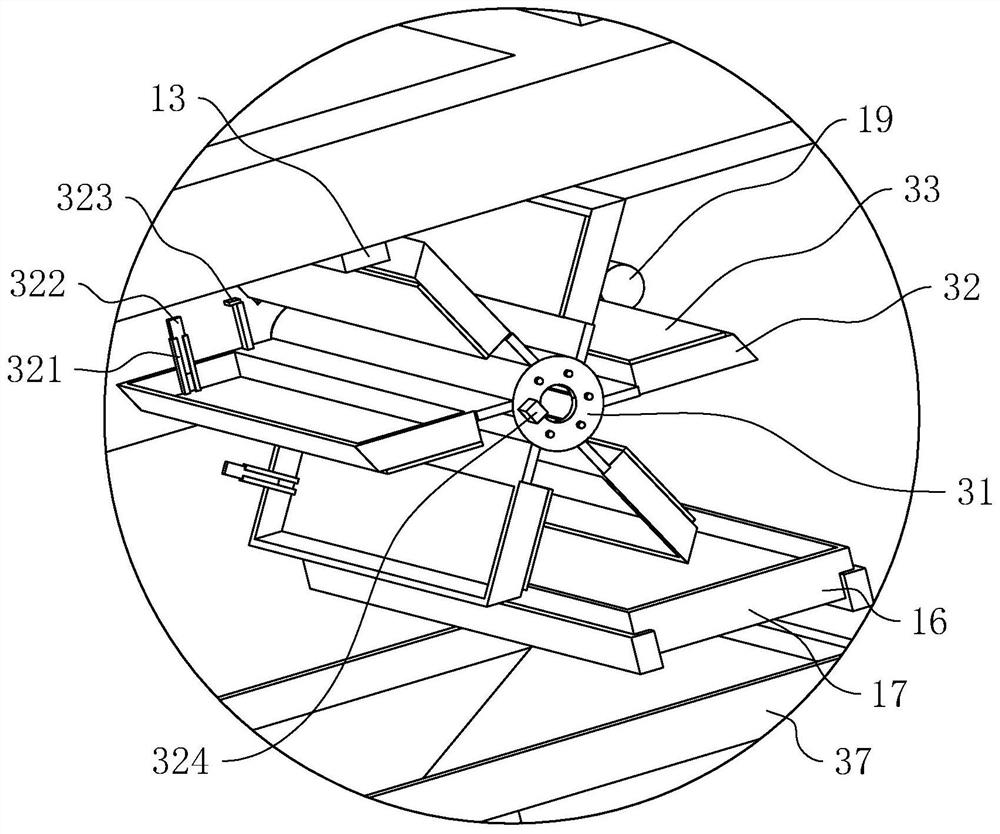
[0045] refer to figure 2 and image 3 , the lower opening of the liquid receiving bucket 13 is a flat rectangle, the frame 1 between the liquid receiving buc...


PUM


Abstract

The invention relates to a numerical control machine tool, and relates to the technical field of the machine tools. The numerical control machine tool includes a machine frame, and a workbench and a cooling pipe are arranged on the machine frame; a hydraulic station is arranged in the machine frame; the workbench is provided with a liquid receiving bucket, a rotating sleeve is rotatably installedon the machine frame under the workbench, the rotating sleeve is provided with six liquid receiving disks at even intervals in the circumferential direction of the rotating sleeve, and when any of theliquid receiving disks is in a horizontal position with an opening upwards, a lower opening of the liquid receiving bucket is located at the position that is the center line of the liquid receiving bucket and is inclined to the side away from the rotating sleeve; an electromagnet is arranged on the lower surface of the liquid receiving bucket; and a collecting bucket is arranged on the machine frame under the liquid receiving disks, the vertical projection of the liquid receiving disks is all in the collecting bucket, and the bottom of the collecting bucket is connected with a liquid outlet pipe leading to the outside of the machine frame. According to the numerical control machine tool, iron chips are attracted by the electromagnet without considering the size of the iron chips, and allthe iron chips can be attracted, so that the iron chip content of cutting liquid falling into the collecting bucket is greatly reduced, the influence on workpieces during reuse can be reduced, and themachining quality is improved.

Description

technical field [0001] The invention relates to the technical field of machine tools, in particular to a numerically controlled machine tool. Background technique [0002] CNC machine tools and turning centers are high-precision, high-efficiency automatic machine tools. Equipped with multi-station turrets or power turrets, the machine tools have a wide range of processing performance, and can process straight cylinders, oblique cylinders, arcs and Various complex workpieces such as threads, grooves, and worms have various compensation functions such as linear interpolation and circular interpolation, and have played a good economic effect in the mass production of complex parts. [0003] The Chinese utility model whose publication number is CN209717151U discloses a new type of CNC machine tool, including a base, a control panel, a machine cover, a glass cover, a cutting fluid recovery pool, a cutting fluid pump, a cutting fluid storage tank, a cutting outlet, and an arc stop...

Claims


Application Information

Patent Timeline
Patent Type & Authority Patents(China)
IPC IPC(8): B23Q11/00B23Q11/10
CPCB23Q11/00B23Q11/0064B23Q11/10
Inventor 赵柯泽赵帅郭琴
Owner 浙江恒大数控装备有限公司
Why Eureka
Try Eureka