
Collision mitigation system and method for bus

A technology for buses and lanes, applied in the field of anti-collision to achieve the effect of protecting safety

Pending Publication Date: 2020-05-19
上海峰华人工智能科技有限公司
View PDF7 Cites 11 Cited by
  • Summary
  • Abstract
  • Description
  • Claims
  • Application Information

AI Technical Summary

Problems solved by technology

[0004] The present invention provides a bus collision mitigation system and method, which solves the above problems

Method used


Image

  • Collision mitigation system and method for bus
  • Collision mitigation system and method for bus
  • Collision mitigation system and method for bus

Examples


Embodiment Construction

[0042] The following will clearly and completely describe the technical solutions in the embodiments of the present invention with reference to the accompanying drawings in the embodiments of the present invention. Obviously, the described embodiments are only some, not all, embodiments of the present invention. Based on the embodiments of the present invention, all other embodiments obtained by persons of ordinary skill in the art without creative efforts fall within the protection scope of the present invention.

[0043] In the description of the present invention, it should be understood that the terms "front", "inside", and "side" indicate orientation or positional relationship, and are only for the convenience of describing the present invention and simplifying the description, rather than indicating or implying the It should not be construed as a limitation on the invention that a component or element must have a specific orientation, be constructed and operate in a speci...


PUM


Abstract

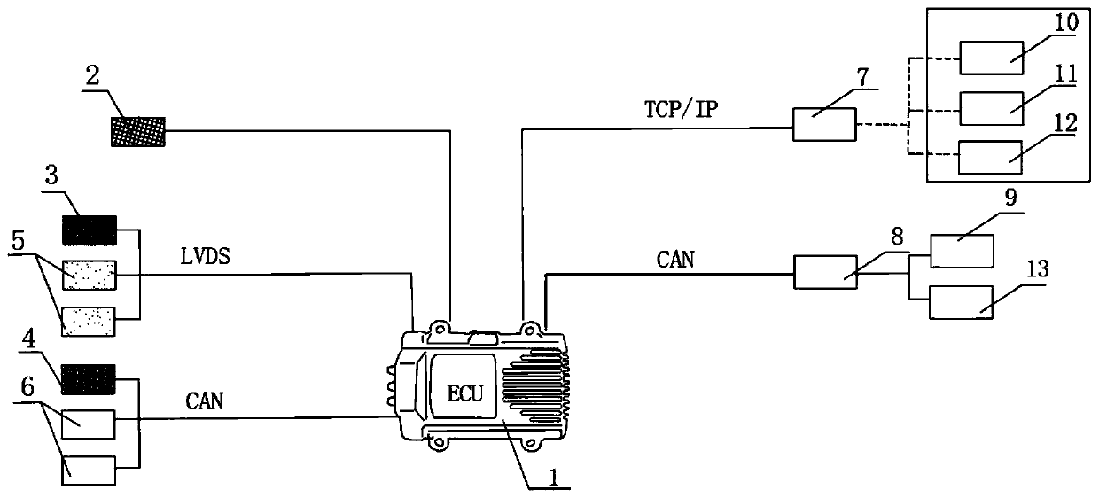
The invention discloses a collision relieving system and method for a bus, and relates to the technical field of automobile collision prevention. The system comprises a first millimeter-wave radar, asecond millimeter-wave radar, a display screen prompter, a first front-facing camera, a second front-facing camera and a fusion host. The first millimeter-wave radar and the second millimeter-wave radar are respectively used for acquiring reflection radar waves of a lane right ahead and lanes on two sides of a vehicle in real time for the image sensor to perform data information identification, and the first front camera and the second front camera are respectively used for acquiring image data of identified targets of the lane right ahead and the lanes on two sides. According to the invention, a driver is ensured not to correctly operate under special conditions, and meanwhile, the control of the automobile is automatically realized, so that the safety of the automobile and the driver isprotected, the accuracy and high efficiency of collision obstacles possibly existing in front are ensured, the recognition blind area is smaller, and the automatic emergency collision braking accuracyis higher.

Description

technical field [0001] The invention belongs to the field of anti-collision technology, and in particular relates to a bus collision mitigation system and a bus anti-collision automatic emergency braking method. Background technique [0002] SAE International's definition of automation level has become the global industry reference standard for defining automated / self-driving vehicles, which is used to evaluate autonomous driving technology. The specific definitions are as follows: L0: The driver is fully in control of the vehicle; L1: The automatic system can sometimes assist The driver completes some driving tasks; L2: the automatic system can complete some driving tasks, but the driver needs to monitor the driving environment to complete the rest; L3: the automatic system can not only complete some driving tasks, but also under certain circumstances Monitor the driving environment, but the driver must be prepared to regain control of the driving (when requested by the aut...

Claims


Application Information

Patent Timeline
Patent Type & Authority Applications(China)
IPC IPC(8): B60T7/12B60T13/74B60W10/18B60W10/20B60W30/09B60W30/18B60W40/105B60W40/107B60W50/14B60W50/16
CPCB60T7/22B60T13/74B60W50/14B60W50/16B60W10/20B60W10/18B60W30/09B60W30/18163B60W40/105B60W40/107B60W2050/143B60W2520/10B60W2520/105B60W2540/10B60W2540/12B60W2710/18B60W2710/20
Inventor 陈贤林
Owner 上海峰华人工智能科技有限公司
Learn More