Heat pipe system for boiler

A boiler and heat pipe technology, which is applied in the field of boiler heat pipe system, can solve the problems of not being able to completely prevent the medium steam from continuing to supply heat and waste heat, and achieve the effect of improving the automation level of boiler heating, high heat transfer efficiency, and fast heat balance

Inactive Publication Date: 2003-06-18
陈烈涛
View PDF4 Cites 3 Cited by
  • Summary
  • Abstract
  • Description
  • Claims
  • Application Information

AI Technical Summary

Problems solved by technology

So that the problem of water scaling that has been overcome has been regenerated in the secondary heater; in addition, when it is necessary to supply heat to multiple devices, since there is no branch heat supply control device, the separate heat pipe supply The thermal system can only rely on the method of shutting off the condensing agent to adjust and control the local heat supply and heat consumption, or adopt the method of adjusting the peak value. continue to supply heat, resulting in heat release waste

Method used


Image

  • Heat pipe system for boiler
  • Heat pipe system for boiler

Examples


Embodiment Construction

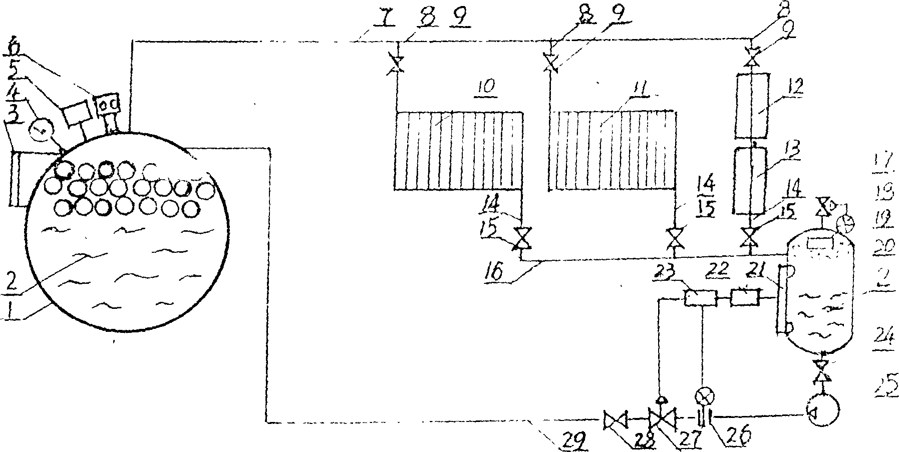
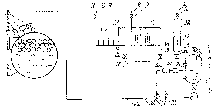
[0015] Such as figure 1 As shown, the present invention includes a boiler body 1 serving as an evaporator, a built-in working medium 2, a liquid level gauge 3, a pressure display control alarm 4, a temperature display control alarm 5 and a safety valve 6. After the boiler 1 is heated, the working medium 2 evaporates rapidly, and the steam enters the heating equipment 10, 11, 12, 13 through the steam flow pipe 7, each branch pipe 8, and the intake valve 9 to condense into a cold liquid with heat release. Heat-using devices 10, 11, 12, 13 acting as condensers, wherein 10 and 11 are connected in parallel, and 12 and 13 are connected in series to form independent branches. A liquid discharge valve 15 is arranged on the condensing return channel 14 of each heating equipment, and the total collecting pipe is 16 . The cold liquid flows in from the upper part of the intermediate storage tank 20 through the return branch pipe I4 and the liquid discharge valve 15 through the collecting...


PUM


Abstract

A heat pipe system is composed of boiler body and partition type heat-consuming equipment and is especially suitable for the condition that the heat supply equipment is far from the heat consuming equipment. The steam branch has regulating valve. In cold liquid channel, there are steam / liquid separating tank, delivery pump of liquid, liquid level regulator and inertial gas exhauster. It has not only the unique advantage of heat pipe in heat transfer, but also has the functions of system pressure and temp. indication, automatic control, and alarm. Its advantages are locally regulated heat consumption, long service life, high efficiency and safety, and saving energy.

Description

Technical field: [0001] The present invention relates to boiler heat supply and heat pipe heat transfer, it is a heat pipe system with a boiler device, especially a separate heat pipe system (system) with a boiler as an evaporator, specifically about a boiler Body and partition heat exchanger——a superconducting heat-transfer heat-combination circulation system composed of heat equipment separated from each other and the boiler body as a separate heat pipe evaporator, and a partition heat exchanger as a separate heat pipe condenser . Background technique: [0002] The existing heat supply system composed of ordinary boiler and partition wall heat exchanger is usually heated by boiler to generate saturated water vapor, which is input into the partition wall heat-consuming equipment through the steam channel, after heat exchange and condensation, it is discharged from the steam trap, and then used The high-pressure water pump returns the condensate and make-up water to the boi...

Claims


Application Information

Patent Timeline
Patent Type & Authority Patents(China)
IPC IPC(8): F24D3/00F28D15/02
Inventor 陈烈涛
Owner 陈烈涛
Why Eureka
Try Eureka