Carrier and light-emitting device

A light-emitting device and carrier technology, applied in the field of lighting, can solve problems such as poor heat resistance

Pending Publication Date: 2020-05-19
SONGSHAN LAKE MATERIALS LAB +1
View PDF0 Cites 0 Cited by
  • Summary
  • Abstract
  • Description
  • Claims
  • Application Information

AI Technical Summary

Problems solved by technology

[0007] In order to improve the problem of poor heat resistance of existing light-emitting diodes, this application proposes a carrier and a light-emitting device

Method used


Image

  • Carrier and light-emitting device
  • Carrier and light-emitting device
  • Carrier and light-emitting device

Examples


Embodiment Construction

[0033] In the present application, all the embodiments, implementations and features of the present application can be combined with each other under the condition of no contradiction or conflict. In this application, conventional equipment, devices, components, etc., can be purchased commercially, or can be self-made according to the content disclosed in this application. In this application, in order to highlight the key points of this application, some conventional operations, equipment, devices, and components are omitted or simply described.

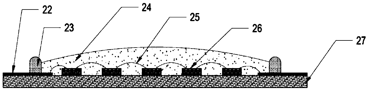
[0034] COB LED refers to a light-emitting diode device in which the chip is directly bonded and packaged on the entire substrate. There are multiple LED chips on the substrate of the device, which are integrated together for packaging. COB LED can be used to solve the problem of manufacturing high-power LED lamps through low-power chips, so it is widely used in bulbs, spotlights, downlights, fluorescent lamps, street lamps, high ba...


PUM


Abstract

The invention discloses a carrier and a light-emitting device, which belong to the field of lighting. The carrier includes an integrally formed substrate and the substrate includes opposing top and bottom surfaces. A box dam is arranged on the top surface of the substrate in a protruding mode, the top surface is provided with an inner side area and an outer side area which are arranged on the twosides of the box dam, the inner side area is provided with a plurality of protruding columns arranged on the top surface in a protruding mode, and each protruding column is provided with a groove formed in the bottom surface. The substrate has an outstanding heat conduction effect, so that thermal quenching can be effectively avoided after the substrate is applied to the light emitting diode.

Description

technical field [0001] The present application relates to the lighting field, in particular, to a carrier and a light emitting device. Background technique [0002] Chip On Board (COB for short) is to adhere the bare chip on the interconnection substrate with conductive or non-conductive adhesive, and then wire bonding to realize electrical connection. Light-emitting diodes based on board chips are also called COB LEDs, and are widely used because of their characteristics. [0003] COB LEDs can be implemented in two ways as described below. [0004] Firstly, the light-emitting chip is arranged on the circuit layer of the substrate, and then a circle of plastic encapsulant is pressed on the periphery of the light-emitting chip to form a dispensing area of ​​phosphor glue. [0005] Second, on the substrate, draw a circle of white silica gel as a dam through a glue dispenser, and then arrange LED chips in the area inside the dam and dispense phosphor glue. [0006] With the ...

Claims


Application Information

Patent Timeline
Patent Type & Authority Applications(China)
IPC IPC(8): H01L33/48H01L33/64H01L33/50H01L33/60H01L33/62H01L25/075
CPCH01L25/0753H01L33/483H01L33/502H01L33/60H01L33/62H01L33/641H01L33/642
Inventor 申小飞曹永革李英魁麻朝阳文子诚王恩哥王充
Owner SONGSHAN LAKE MATERIALS LAB
Why Eureka
Try Eureka