Resonant cavity structure based on magneto-optical effect and laser

A magneto-optical effect and resonant cavity technology, applied in the field of lasers, can solve problems such as troublesome operation, and achieve the effect of improving stability and changing power

Pending Publication Date: 2020-05-19
XIAMEN UNIV OF TECH
View PDF0 Cites 0 Cited by
  • Summary
  • Abstract
  • Description
  • Claims
  • Application Information

AI Technical Summary

Problems solved by technology

Its main disadvantage is that the transmittance of the existing output mirrors is fixed and cannot be changed randomly
If you want to change the output rate of the laser, you must replace the output mirror, which is very troublesome to operate and requires professional laser technicians

Method used


Image

  • Resonant cavity structure based on magneto-optical effect and laser
  • Resonant cavity structure based on magneto-optical effect and laser
  • Resonant cavity structure based on magneto-optical effect and laser

Examples


Embodiment 1

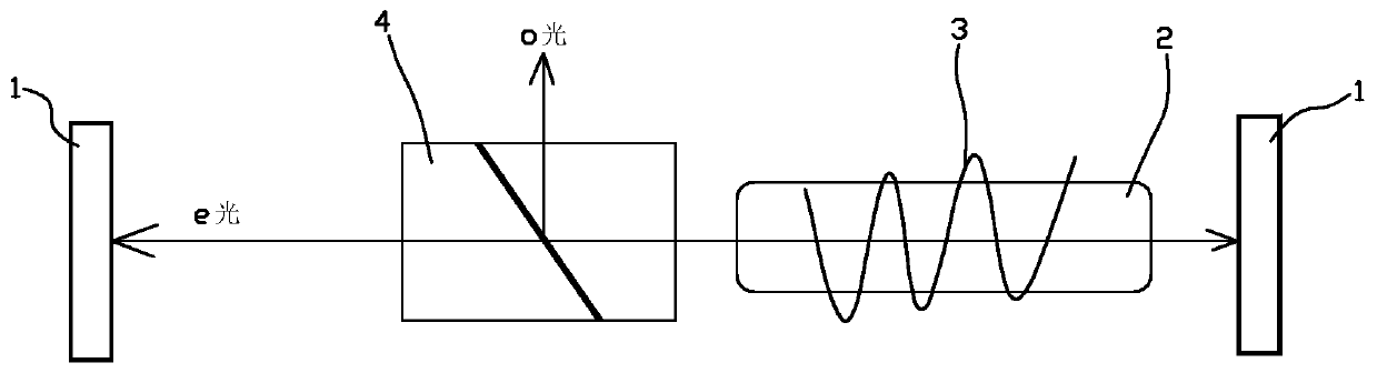
[0021] refer to figure 1 As shown, a kind of resonant cavity structure based on the magneto-optical effect provided by the present embodiment includes: two laser high reflection mirrors 1 arranged at intervals and a polarization device and a magnetic field generator ( not shown) and magneto-optical material body 2. Specifically, the resonant cavity is a linear resonant cavity, and the two laser high-reflection mirrors 1 are arranged opposite to each other. The incident beam is reflected by the two laser high-reflection mirrors 1 to oscillate and amplify in the resonant cavity to form an oscillating beam (ie, e-light). The polarizer is a Glan-Taylor prism 4 , and the oscillating light beam (ie, e-light) can propagate through the Glan-Taylor prism 4 and the magneto-optical material body 2 .

[0022] The magnetic field generator corresponds to the magneto-optical material body 2, and the magnetic field 3 generated by the magnetic field generator has a certain component in the di...

Embodiment 2

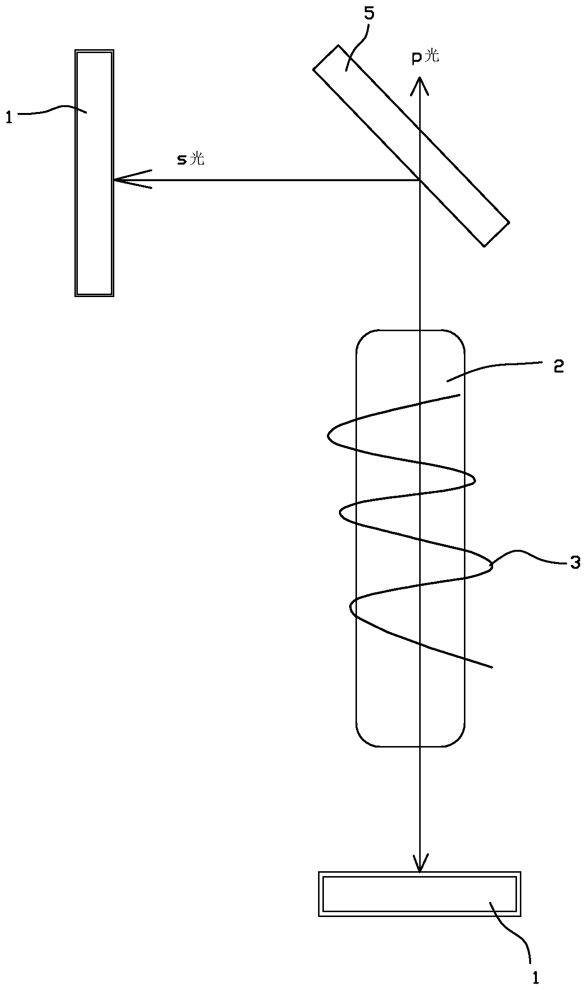
[0030] refer to figure 2 As shown, a kind of resonant cavity structure based on the magneto-optical effect provided by the present embodiment includes: two laser high reflection mirrors 1 arranged at intervals and a polarization device and a magnetic field generator ( not shown) and magneto-optical material body 2. Specifically, the resonant cavity is an "L" shaped resonant cavity, and two high-reflection laser mirrors 1 are respectively arranged at the two ends of the "L" shaped resonant cavity, and the polarizing device is a polarizing beam splitter 5, and the polarizing beam splitting mirror 5 is set At the corner position of the "L" shaped resonator. The incident light beam is refracted by the polarizing beam splitter 5, so as to reflect and oscillate back and forth between the two laser high reflection mirrors 1 to form an oscillating light beam (s-ray in this embodiment).

[0031] The magnetic field generator corresponds to the magneto-optical material body 2, and the...

Embodiment 3

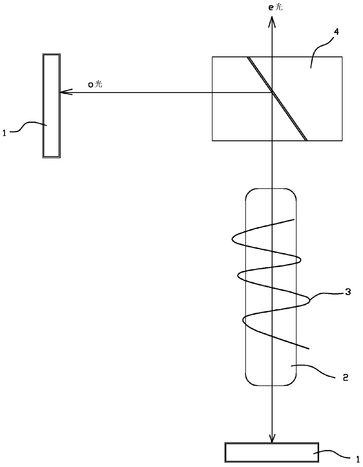
[0040] refer to image 3 As shown, a kind of resonant cavity structure based on the magneto-optical effect provided by the present embodiment includes: two laser high reflection mirrors 1 arranged at intervals and a polarization device and a magnetic field generator ( not shown) and magneto-optical material body 2. Specifically, the resonant cavity is an "L" shaped resonant cavity, two laser high reflection mirrors 1 are respectively arranged at the two ends of the "L" shaped resonant cavity, the polarizing device is a Glan Taylor prism 4, and the Glan Taylor prism 4 is set at the corner position of the "L" shaped resonant cavity. The incident light beam is refracted by the Glan-Taylor prism 4, so as to reflect and oscillate back and forth between the two laser high reflection mirrors 1 to form an oscillating light beam (o-ray in this embodiment).

[0041] The magnetic field generator corresponds to the magneto-optical material body 2, and the magnetic field 3 generated by t...


PUM


Abstract

The invention relates to a resonant cavity structure based on a magneto-optical effect and a laser with the resonant cavity. The resonant cavity structure based on the magneto-optical effect comprisestwo laser high-reflectivity mirrors which are arranged at an interval, and a polarization device, a magnetic field generator and a magneto-optical material body which are arranged between the two laser high-reflectivity mirrors, wherein the magnetic field generator corresponds to the magneto-optical material body; a magnetic field generated by the magnetic field generator has a certain componentin the propagation direction of the oscillating beam at the current position; the magneto-optical material body changes the polarization direction of the oscillation light beam under the action of a magnetic field, and the oscillation light beam with the polarization direction changed by the magneto-optical material body is separated by the polarization device into an oscillation light beam whichcontinues to be oscillated and amplified in the resonant cavity and an output light beam which is separated from the resonant cavity to be output. The intensity of the output light beam is related tothe magnetic field intensity, the transmittance of the output light beam can be changed by changing the magnetic field intensity, and parts do not need to be replaced.

Description

technical field [0001] The invention relates to the field of lasers, in particular to a resonant cavity structure based on the magneto-optic effect and a laser with the resonant cavity. Background technique [0002] A laser is generally composed of three parts: a pump source, a laser working medium and a resonant cavity. The resonant cavity is composed of an input mirror and an output mirror. The input mirror is coated with a laser high-reflection film, which is a laser high-reflection mirror; while the laser output mirror is coated with a partial reflection film (that is, has a partial transmittance). The partial reflection of the output mirror is to continuously oscillate and amplify the laser in the resonant cavity, while the transmission is to realize the laser output. Most of the existing laser output mirrors are partially reflected by coating. Its main disadvantage is that the transmittance of the existing output mirrors is fixed and cannot be changed randomly. If y...

Claims


Application Information

Patent Timeline
Patent Type & Authority Applications(China)
IPC IPC(8): H01S3/10H01S3/106H01S3/08
CPCH01S3/08H01S3/10061H01S3/1066
Inventor 林洪沂阮剑剑孙栋刘虹刘加梁黄晓桦
Owner XIAMEN UNIV OF TECH
Why Eureka
Try Eureka