
Dispatching master station-oriented power grid frequency disturbance source positioning method

A disturbance source location and power grid frequency technology, applied in the direction of reducing/preventing power oscillations, can solve hidden dangers in power grid security, affect the normal operation of the power grid, and achieve rapid and effective positioning

Active Publication Date: 2020-05-19
NR ELECTRIC CO LTD +2
View PDF2 Cites 1 Cited by
  • Summary
  • Abstract
  • Description
  • Claims
  • Application Information

AI Technical Summary

Problems solved by technology

[0002] During the operation of the power grid, system failure (test) or DC unblocking, new energy output or large user load fluctuations, and power plant output fluctuations will all cause system frequency fluctuations. The first two types of factors can be known in advance or easily discovered, while power plant output fluctuations It often takes a lot of analysis after the event to be discovered. If it is not discovered in time, it may cause hidden dangers to the safety of the power grid and affect the normal operation of the power grid. Therefore, when the frequency disturbance is caused by the output fluctuation of the power plant, quickly and effectively locating the disturbance source of the power plant is very important to the dispatcher. It is of great significance, but there are many power plants and units in the power grid, it is difficult for the dispatcher to quickly find out the disturbance source, and it is impossible to take further measures to eliminate the fluctuation in time

Method used


Image

  • Dispatching master station-oriented power grid frequency disturbance source positioning method
  • Dispatching master station-oriented power grid frequency disturbance source positioning method

Examples


Embodiment Construction

[0018] The technical solutions and beneficial effects of the present invention will be described in detail below in conjunction with the accompanying drawings.

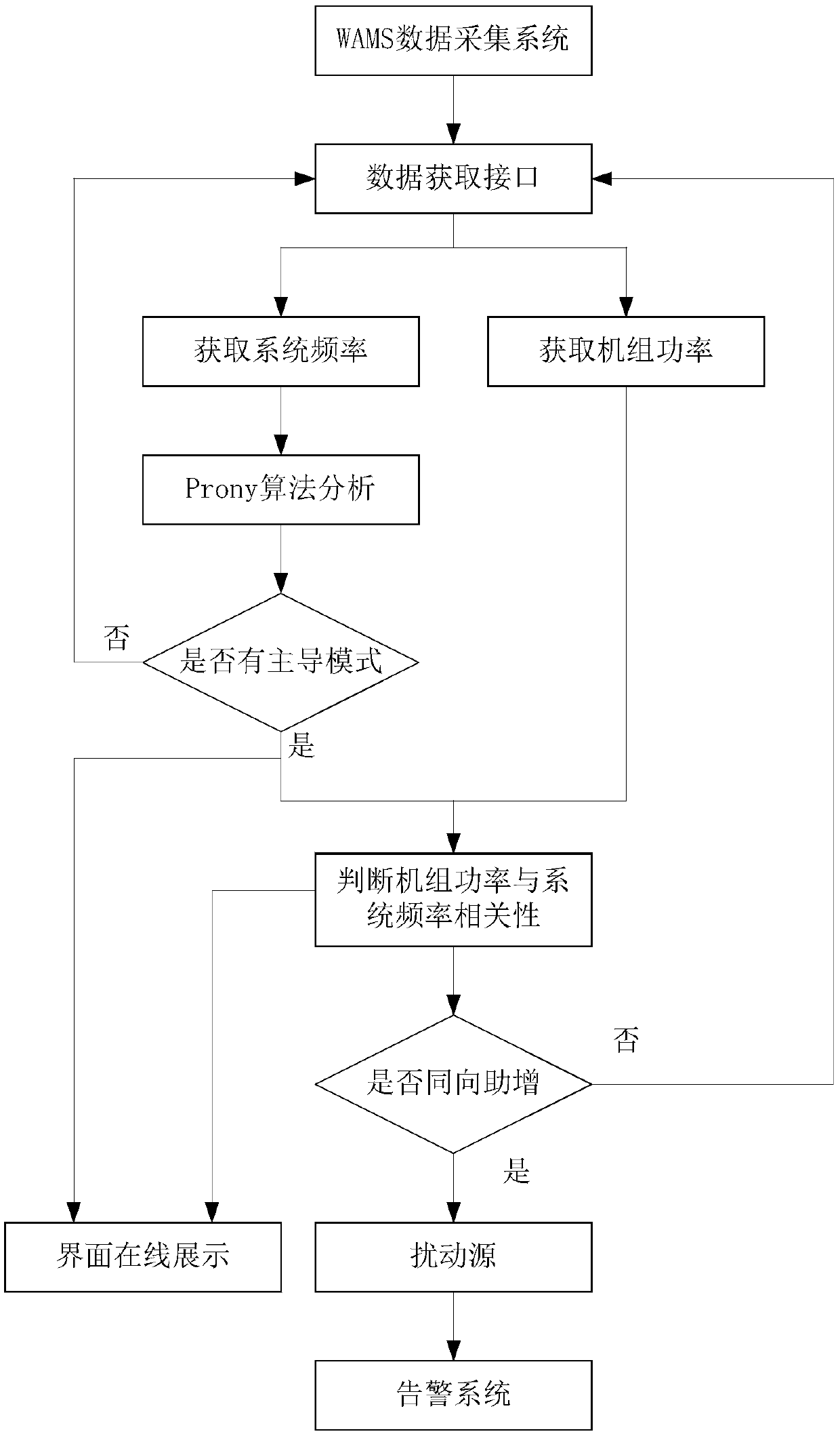
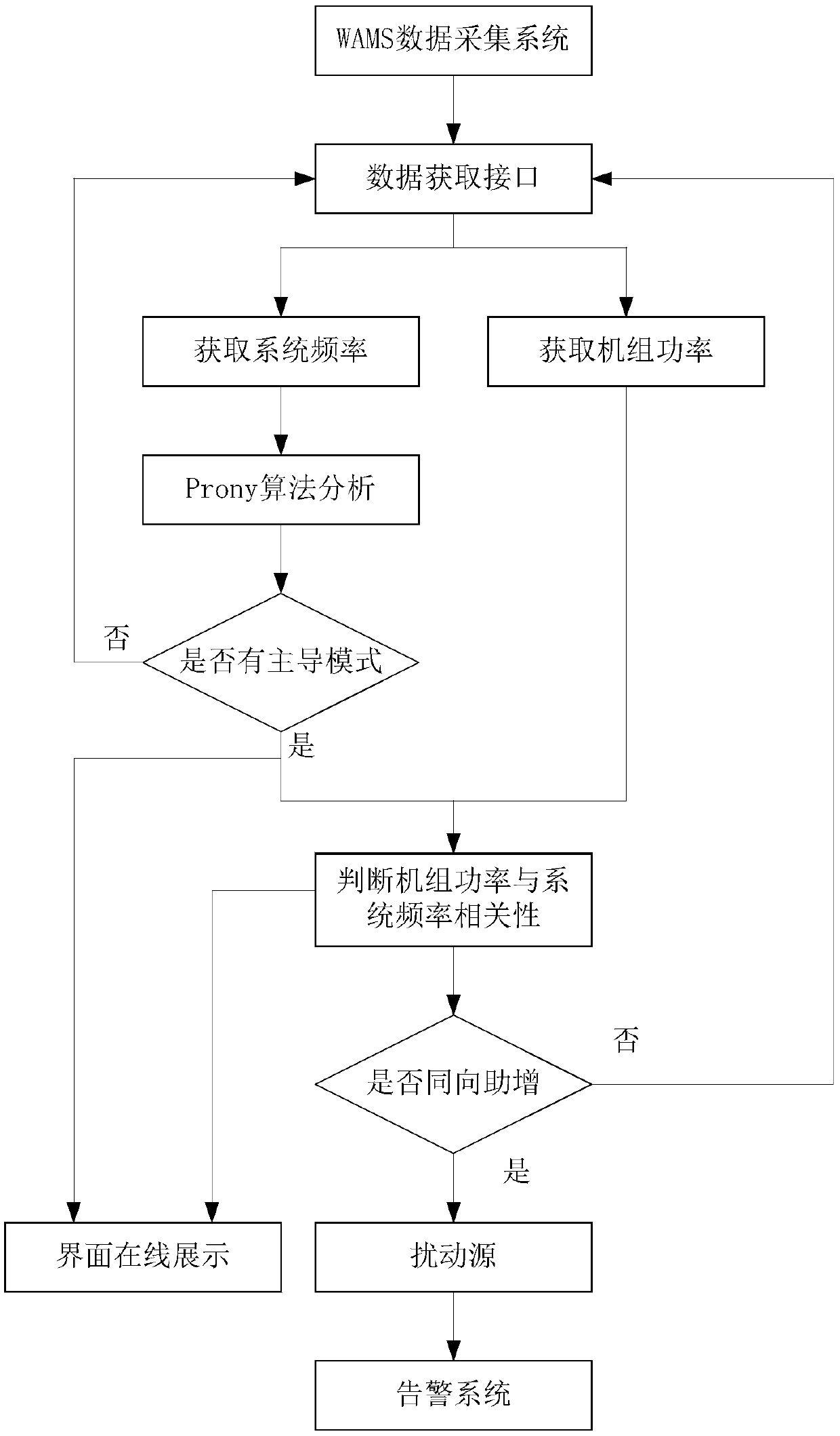
[0019] like figure 1 As shown, the present invention provides a method for locating power grid frequency disturbance source oriented to the dispatching master station, comprising the following steps:

[0020] A: Use the existing WAMS data acquisition system to obtain the system frequency and power plant unit power in the whole region, and form a system frequency and power plant unit power parameter library. Among them, the data collected by WAMS needs to be obtained through the data interface, and the system frequency is the unified frequency in the power grid , the unit power of the power plant comes from the units under all power plants in the system collected by the PMU, and the data are millisecond-level real-time data;

[0021] B: According to the system frequency data obtained in step A, determine the analysis ...


PUM


Abstract

The invention discloses a dispatching master station-oriented power grid frequency disturbance source positioning method. The method comprises the following steps of: acquiring full-area system frequency and power plant unit power by using a WAMS data acquisition system to form a system frequency and power plant unit power parameter library; according to the system frequency data, distinguishing the system frequency by adopting a prony algorithm to obtain a dominant mode disturbance frequency, a disturbance amplitude and a damping ratio, and judging whether frequency disturbance occurs in thesystem or not according to the dominant mode disturbance frequency, the disturbance amplitude and the damping ratio; and if the frequency disturbance occurs, obtaining the correlation between the system frequency and the power data trend of each unit, determining the assistant increasing attribute of the unit power to the system frequency through the correlation, and determining the unit or the unit group causing the disturbance to the system frequency through the correlation sorting on the premise of the assistant increasing attribute so as to judge the disturbance source. The method can quickly and effectively position the disturbance source of the power plant, specifically arrives at the unit, provides decision-making assistance for the next action of a dispatcher, and guarantees the normal and safe operation of a power grid.

Description

technical field [0001] The invention belongs to the technical field of power system safety and stability monitoring, relates to frequency fluctuation monitoring based on WAMS, and in particular to a method for locating frequency disturbance sources of a power grid oriented to a dispatching master station. Background technique [0002] During the operation of the power grid, system failure (test) or DC unblocking, new energy output or large user load fluctuations, and power plant output fluctuations will all cause system frequency fluctuations. The first two types of factors can be known in advance or easily discovered, while power plant output fluctuations It often takes a lot of analysis after the event to be discovered. If it is not discovered in time, it may cause hidden dangers to the safety of the power grid and affect the normal operation of the power grid. Therefore, when the frequency disturbance is caused by the output fluctuation of the power plant, quickly and effe...

Claims


Application Information

Patent Timeline
Patent Type & Authority Applications(China)
IPC IPC(8): H02J3/24
CPCH02J3/24
Inventor 袁飞飞张孝施雄华范磊
Owner NR ELECTRIC CO LTD
Learn More