
Hydraulic brake device

A technology of hydraulic brakes and brake discs, which is applied in the direction of brake actuators, gear transmission mechanisms, axial brakes, etc., and can solve problems such as incompressibility, inability to achieve rapid braking, and small braking force

Pending Publication Date: 2020-05-22
SHENZHEN YAKANGCHENG TECH DEV CO LTD
View PDF0 Cites 1 Cited by
  • Summary
  • Abstract
  • Description
  • Claims
  • Application Information

AI Technical Summary

Problems solved by technology

[0002] In the existing hydraulic braking system, most of the hydraulic pumps are connected by closed pipelines. When the pressure of the brake master cylinder acts on the brake fluid, the liquid is incompressible and transmits the pressure to the brake cylinder, so that the cylinder in the cylinder The piston stretches to both sides under the action of liquid pressure, pushing the brake pads and brake discs to generate braking force, and this braking method usually only has one braking surface, and the braking force generated is relatively small, resulting in The response time of the brake is long, and the effect of rapid braking cannot be achieved

Method used


Image

  • Hydraulic brake device
  • Hydraulic brake device
  • Hydraulic brake device

Examples


Embodiment Construction

[0027] The following will clearly and completely describe the technical solutions in the embodiments of the present invention with reference to the accompanying drawings in the embodiments of the present invention. Obviously, the described embodiments are only part of the embodiments of the present invention, not all of them. Based on the embodiments of the present invention, all other embodiments obtained by persons of ordinary skill in the art without making creative efforts belong to the protection scope of the present invention.

[0028] It should be noted that all directional indications (such as up, down, left, right, front, back...) in the embodiments of the present invention are only used to explain the relationship between the components in a certain posture (as shown in the accompanying drawings). Relative positional relationship, movement conditions, etc., if the specific posture changes, the directional indication will also change accordingly.

[0029] In the prese...


PUM


Abstract

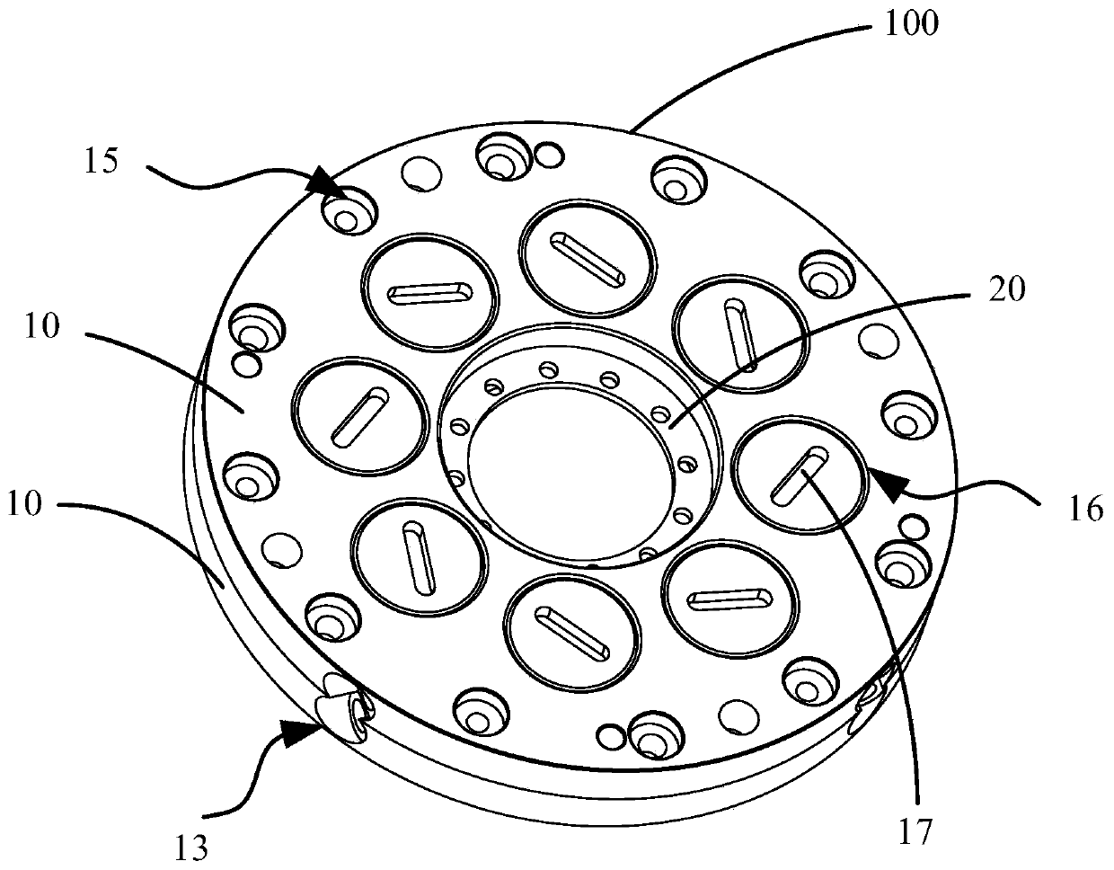
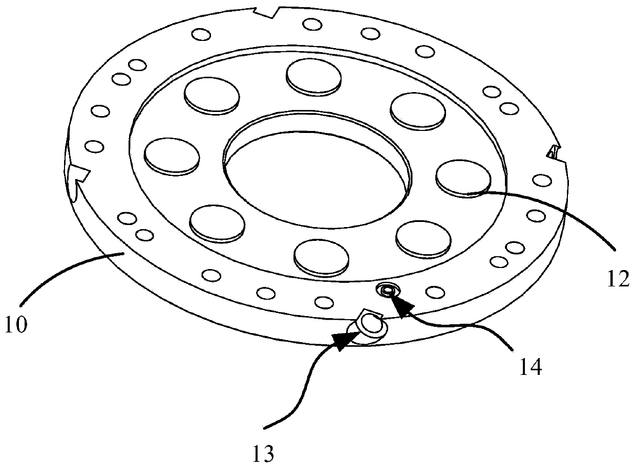
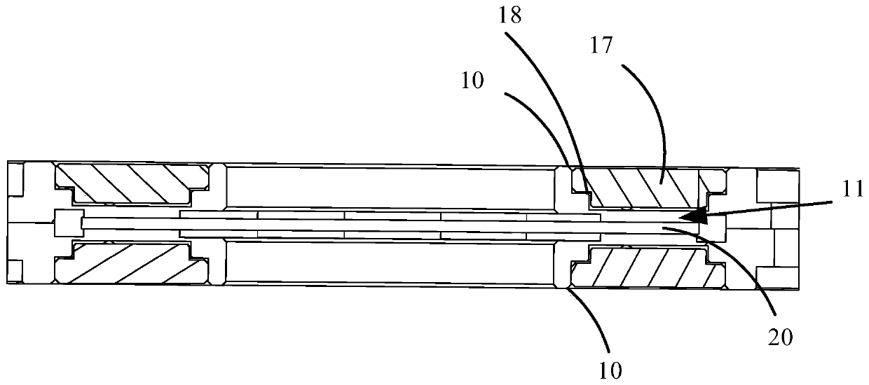
The invention discloses a hydraulic brake device. The hydraulic brake device comprises two brake discs and a brake pad, the two brake discs are oppositely arranged and connected with each other, cavities are formed in the brake discs, and the two cavities are in communication with each other; mounting grooves are concavely formed in the surface, facing the other brake disc, of one brake disc, thetwo mounting grooves are oppositely formed and define a mounting space, brake bosses are convexly arranged on the bottom walls of the mounting grooves, the interiors of the brake bosses are in communication with the cavities, the two brake bosses are oppositely arranged, and oil filling holes communicated with the cavity are formed in any brake disc; the brake pad is arranged in the mounting spaceand located between the two brake bosses, the protruding ends of the brake bosses face the brake pad, and the surfaces, facing the brake pad, of the brake bosses can be close to or away from the brake pad so as to lock or release the brake pad. According to the hydraulic brake device, the braking force of the braking device is increased so as to shorten the braking response time.

Description

technical field [0001] The invention relates to the technical field of brake equipment, in particular to a hydraulic brake device. Background technique [0002] In the existing hydraulic braking system, most of the hydraulic pumps are connected by closed pipelines. When the pressure of the brake master cylinder acts on the brake fluid, the liquid is incompressible and transmits the pressure to the brake cylinder, so that the cylinder in the cylinder The piston stretches to both sides under the action of liquid pressure, pushing the brake pads and brake discs to generate braking force, and this braking method usually only has one braking surface, and the braking force generated is relatively small, resulting in The response time of the brake is long, and the effect of rapid braking cannot be achieved. [0003] The above content is only used to assist in understanding the technical solution of the present application, and does not mean that the above content is admitted as pr...

Claims


Application Information

Patent Timeline
Patent Type & Authority Applications(China)
IPC IPC(8): F16D55/22F16D65/12F16D65/14F16D121/04
CPCF16D55/22F16D65/12F16D65/14F16D2121/04
Inventor 闫娟
Owner SHENZHEN YAKANGCHENG TECH DEV CO LTD
Learn More