Heat insulation rail weighbridge for molten iron weighing and laying method thereof

A rail scale, molten iron technology, applied in the detailed information of weighing equipment, weighing equipment with special properties/forms, weighing, etc. Track scale damage and other problems, to achieve the effect of extending service life, ensuring independence requirements, and low cost

Pending Publication Date: 2020-05-22
新余钢铁股份有限公司
View PDF0 Cites 0 Cited by
  • Summary
  • Abstract
  • Description
  • Claims
  • Application Information

AI Technical Summary

Problems solved by technology

However, in the prior art, many ironworks use traditional track scales, and there is a certain gap between the weighing platform and the surrounding of the traditional track scales. If metallurgical high-temperature hot-melt molten iron or molten steel leaks or splashes into it, if it is stuck with the weighing platform , it will affect the accurate weighing of the metering system, and the heat radiation (baking) generated by metallurgical high-temperature melting will also cause damage to the track scale. In the prior art, refractory bricks are laid on the surface of the track scale to prevent metallurgical high-temperature melting The damage caused to the track scale, but the laying of refractory bricks on the weighing platform will cause unevenness and structural instability, so the reliable, accurate and stable operation of the weighing and measuring system in high temperature and harsh environments cannot be guaranteed

Method used


Image

  • Heat insulation rail weighbridge for molten iron weighing and laying method thereof
  • Heat insulation rail weighbridge for molten iron weighing and laying method thereof
  • Heat insulation rail weighbridge for molten iron weighing and laying method thereof

Examples


Embodiment Construction

[0027] In order to make the purpose, technical solutions and advantages of the embodiments of the present invention more clear, the technical solutions in the embodiments will be clearly and completely described below in conjunction with the drawings in the embodiments of the present invention. The following embodiments are used to illustrate the present invention , but not to limit the scope of the present invention.

[0028] In the description of the present invention, it should be noted that unless otherwise specified and limited, the terms "installation", "connection" and "connection" should be understood in a broad sense, for example, it can be a fixed connection or a detachable connection. Connected, or integrally connected; it may be mechanically connected or electrically connected; it may be directly connected or indirectly connected through an intermediary. Those of ordinary skill in the art can understand the specific meanings of the above terms in the present invent...


PUM

PropertyMeasurementUnit
thicknessaaaaaaaaaa
thicknessaaaaaaaaaa
thicknessaaaaaaaaaa

Abstract

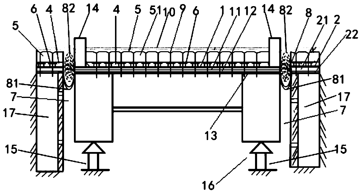
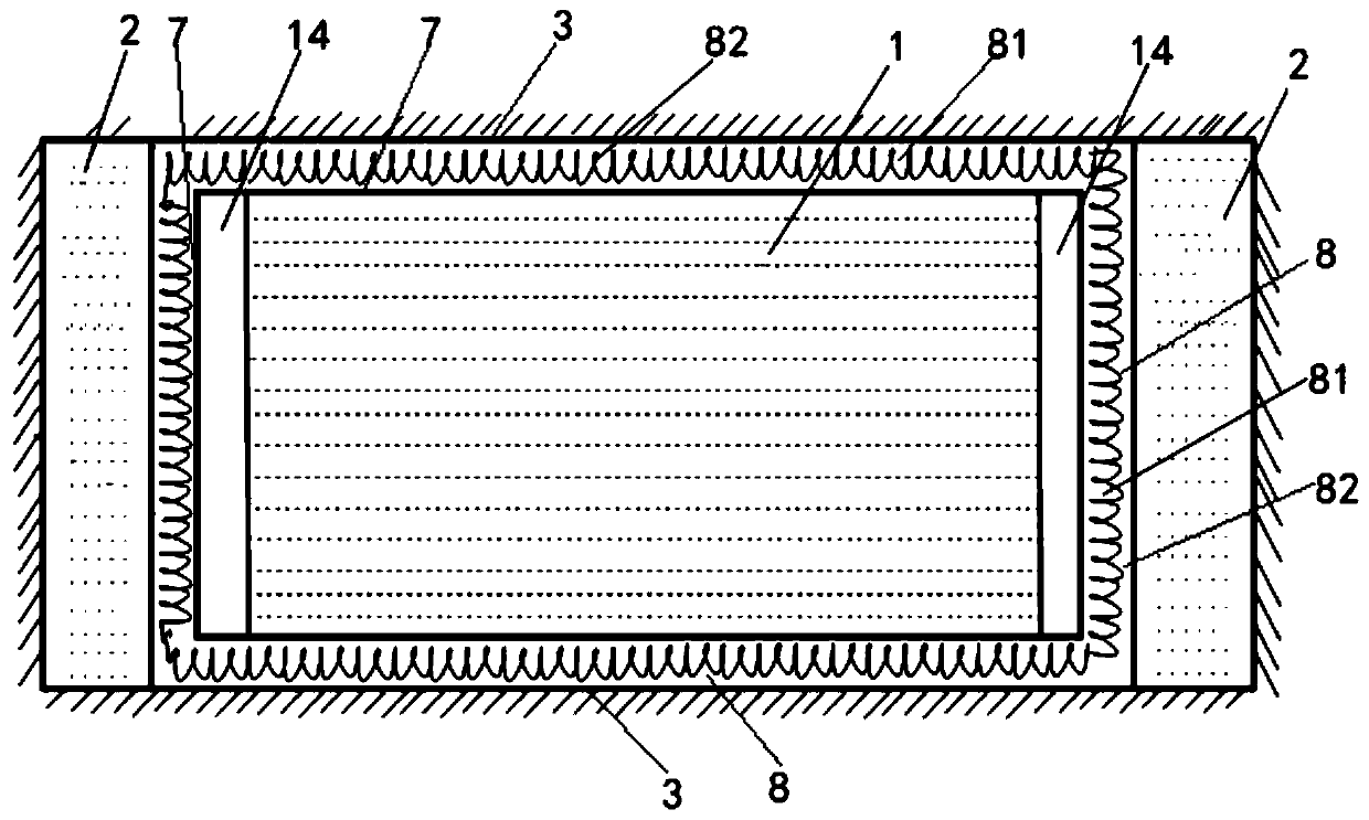
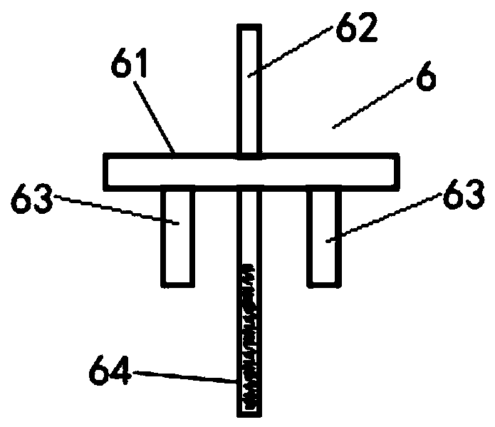
The invention discloses a heat insulation rail weighbridge for molten iron weighing and a laying method thereof, and belongs to the technical field of ferrous metallurgy high-temperature hot melting weighing. The heat insulation rail weighbridge for molten iron weighing comprises a weighing platform, supporting platforms and foundation walls. The supporting platforms are arranged at the two sidesof the weighing platform respectively, the foundation walls are arranged at the two ends of the weighing platform respectively, and the weighing platform is hermetically and flexibly connected with the supporting platforms and the foundation walls. The weighing platform and the supporting platforms are respectively provided with a thermal insulation layer and a heat-resisting layer, and a plurality of segmentation parts are uniformly distributed in the heat insulation layer and form a bearing platform for bearing the heat-resisting layer. The beneficial effects of the present invention are that the heat insulation rail weighbridge for molten iron weighing is stable in overall structure and long in service life and is resistant to high temperature; the molten iron is prevented from splashing into the gaps around the weighing platform; the rail weighbridge cannot be damaged under the conditions of molten iron heat radiation and little leakage, and the reliable, accurate and stable operation of a weighing and metering system is guaranteed.

Description

technical field [0001] The invention relates to the technical field of iron and steel metallurgy high-temperature hot-melt weighing, in particular to a heat-insulated track scale for weighing molten iron and a laying method thereof. Background technique [0002] Weighing of molten iron in the blast furnace is necessary during the tapping process. First, it can control the amount of iron tapping. Second, it can know the actual delivery amount of each pot. Third, it can be used as the basis for the swing of the swing chute. However, in the prior art, many ironworks use traditional track scales, and there is a certain gap between the weighing platform and the surrounding of the traditional track scales. If metallurgical high-temperature hot-melt molten iron or molten steel leaks or splashes into it, if it is stuck with the weighing platform , it will affect the accurate weighing of the metering system, and the heat radiation (baking) generated by metallurgical high-temperature ...

Claims


Application Information

Patent Timeline
Patent Type & Authority Applications(China)
IPC IPC(8): G01G17/04G01G21/22
CPCG01G17/04G01G21/22
Inventor 肖兴华吴盛虎周文广朱忠琼
Owner 新余钢铁股份有限公司
Why Eureka
Try Eureka