Steel-carbon fiber composite material explosion-proof shell structure

A technology of composite materials and flameproof enclosures, which is applied in the direction of electrical equipment enclosures/cabinets/drawers, casings/cabinets/drawer parts, electrical components, etc., which can solve the problems of large dispersion of bonding strength, thick and large loads, Non-removable and other issues, to achieve strong resistance to peeling stress and splitting stress, ensure locking strength, and prevent fine vibrations

Inactive Publication Date: 2020-05-22
安徽玄离智能科技股份有限公司
View PDF8 Cites 0 Cited by
  • Summary
  • Abstract
  • Description
  • Claims
  • Application Information

AI Technical Summary

Problems solved by technology

[0002] At present, the adhesive connection is the most widely used load transfer method for composite material structural connections. Its disadvantages are as follows: First, there is a lack of reliable non-destructive testing methods, the quality control of the bonding is difficult, the reliability is poor, the bonding strength is highly dispersed, and the peeling strength is relatively low. Low, it is difficult to transmit large loads; second, the bonding performance is greatly affected by the environment such as humidity, heat, and corrosive media, and there is a certain aging problem. The bonding surface needs special surface treatment before bonding, and the process requirements are strict. The matching tolerance between the glued parts is strict, and heating and pressure curing equipment is required. It is difficult to repair. The glued joint is a permanent link and cannot be disassembled after being glued. It is difficult to recycle and reuse materials. load;

Method used


Image

  • Steel-carbon fiber composite material explosion-proof shell structure
  • Steel-carbon fiber composite material explosion-proof shell structure
  • Steel-carbon fiber composite material explosion-proof shell structure

Examples


Embodiment Construction

[0019] In order to make the technical means, creative features, goals and effects achieved by the present invention easy to understand, the present invention will be further described below in conjunction with specific embodiments.

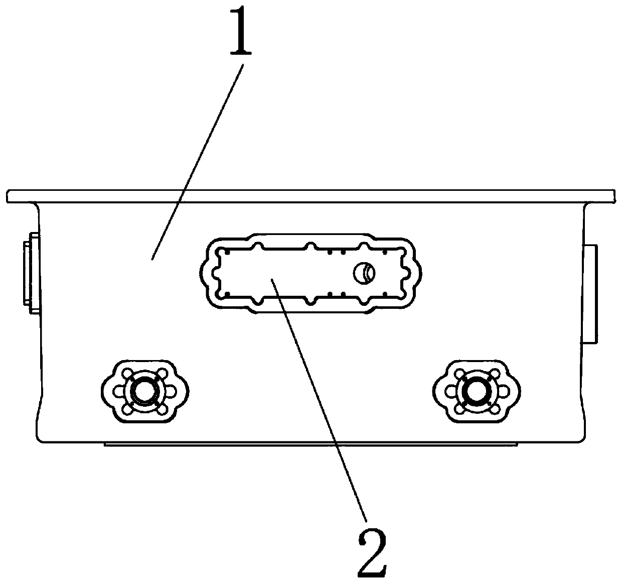
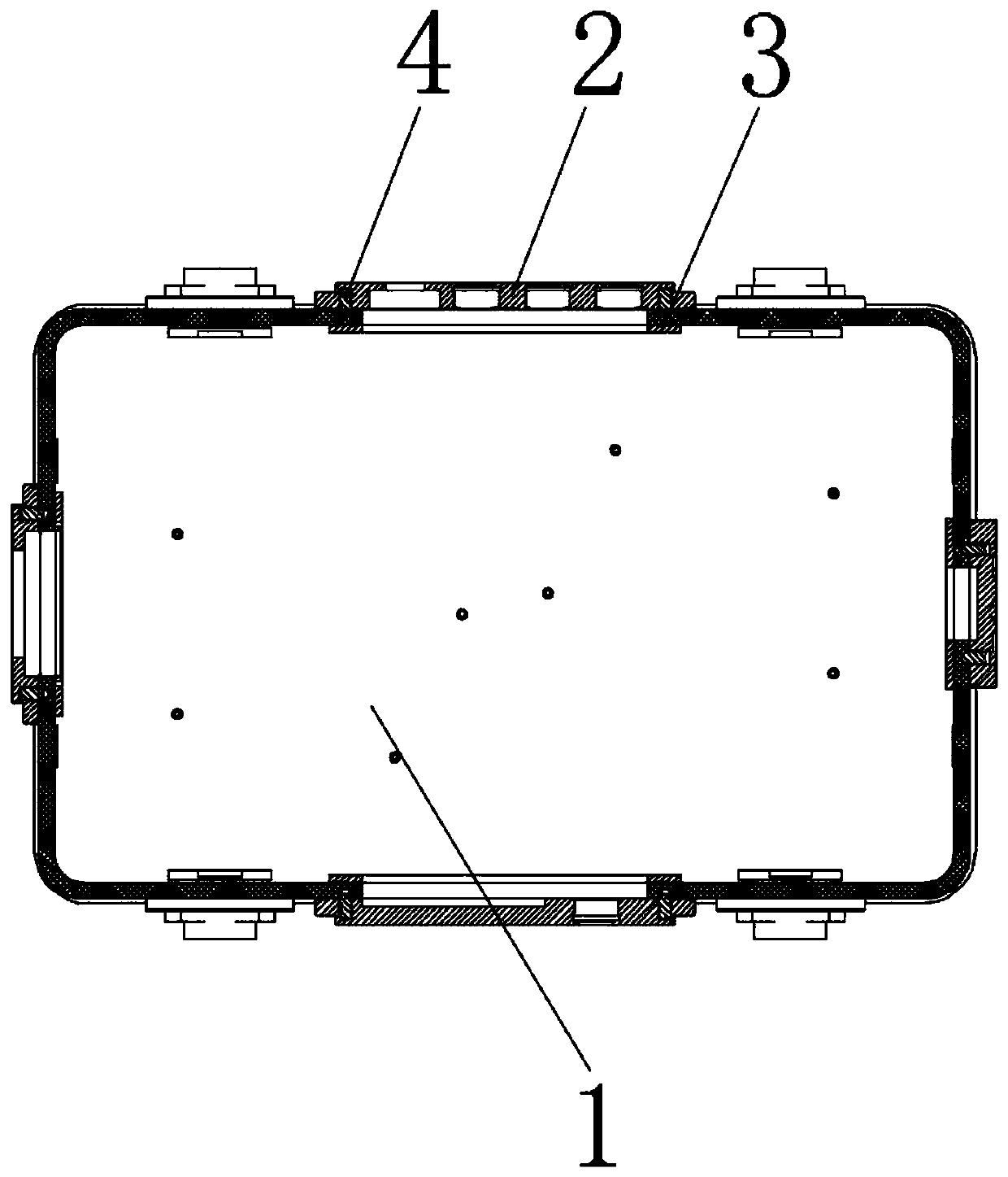
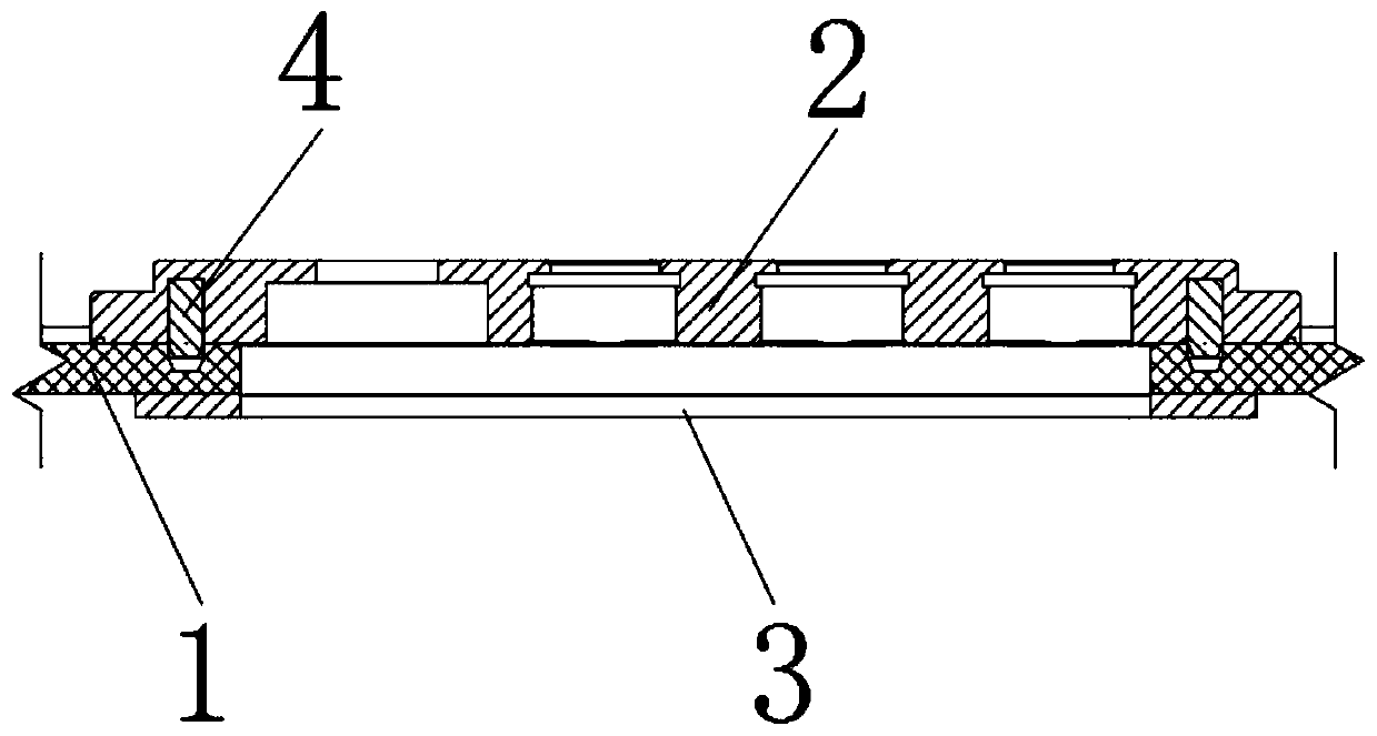
[0020] refer to Figure 1-3 As shown, a steel-carbon fiber composite flameproof shell structure includes a carbon fiber composite shell 1, the outer surface of the carbon fiber composite shell 1 is provided with a plurality of rectangular holes, and the inner and outer surfaces of the carbon fiber composite shell 1 are respectively close to the rectangular holes The edge position is provided with positioning pin holes and positioning pins 4 for fixing steel connectors, wherein,

[0021] The steel connecting piece includes a steel structural part 2 installed on the outer surface of the carbon fiber composite material shell 1 near the edge of the rectangular hole for the functional parts of the carbon fiber composite material shell 1 and installed o...


PUM


Abstract

The invention discloses a steel-carbon fiber composite material explosion-proof shell structure which comprises a carbon fiber composite material shell, a plurality of rectangular holes are formed inthe outer surface of the carbon fiber composite material shell, and positioning pin holes and positioning pins are arranged at the positions, close to the rectangular holes, of the inner surface and the outer surface of the carbon fiber composite material shell respectively. According to the steel-carbon fiber composite material explosion-proof shell structure, the steel connecting piece is connected with the carbon fiber composite material through a bolt, the connection is a a through-thickness connection, peeling stress and splitting stress can be resisted, the quality is convenient to check, and the connection reliability is ensured; the steel-carbon fiber composite material explosion-proof shell structure can be repeatedly assembled and disassembled during manufacturing, replacement and maintenance; the steel-carbon fiber composite material explosion-proof shell structure has low requirements on preparation and treatment of the connecting surface of a part, has no residual stress generated by cementing solidification, is less influenced by the environment, and has no thickness limitation; and the structure of a positioning pin is adopted, the positioning precision of the part can be gauranteed, fine vibration of a steel structural part is prevented, and the locking strength is ensured.

Description

technical field [0001] The invention relates to the technical field of flameproof enclosures, in particular to a steel-carbon fiber composite flameproof enclosure structure. Background technique [0002] At present, the adhesive connection is the most widely used load transfer method for composite material structure connections. Its disadvantages are as follows: First, there is a lack of reliable non-destructive testing methods, the quality control of the bonding is difficult, the reliability is poor, the bonding strength is highly dispersed, and the peeling strength is relatively low. Low, it is difficult to transfer large loads; second, the bonding performance is greatly affected by the environment such as humidity, heat, and corrosive media, and there is a certain aging problem. The bonding surface needs special surface treatment before bonding, and the process requirements are strict. The matching tolerance between the glued parts is strict, and heating and pressure curi...

Claims


Application Information

Patent Timeline
Patent Type & Authority Applications(China)
IPC IPC(8): H05K5/02
CPCH05K5/0217
Inventor 张梅
Owner 安徽玄离智能科技股份有限公司
Why Eureka
Try Eureka