


Quick Research
Generate reliable direction feasibility study reports for your R&D in just a few steps.

Technical Q&A
Discover and master advanced knowledge NOW. Basics, ideas, possibilities, all at once.

Find Solutions
As an expert in R&D theories, this can generate solutions to your technical problems instantly.

Evaluate Feasibility
Analyze your overall solution with one click, know your potential R&D risks in advance.

Monitor Landscape
Get weekly tech updates, stay abreast of the latest tech innovations and key insights.
Bottom hole type crucible induction smelting gas atomization powdering device and method
A pulverizing device and atomized pulverizing technology, which is applied in the fields of gas atomized pulverizing and metal additive manufacturing, and can solve problems that do not involve the technical points of gas atomized pulverizing, scalding of atomizing nozzles or equipment, and liquid guiding. The problem of poor fit between the tube and the plug rod is achieved, and the assembly method is simple and effective, reducing heat transfer to the outside, and reducing the coating workload.
- Summary
- Abstract
- Description
- Claims
- Application Information
AI Technical Summary
Problems solved by technology
Method used
Image

Examples
Embodiment 1
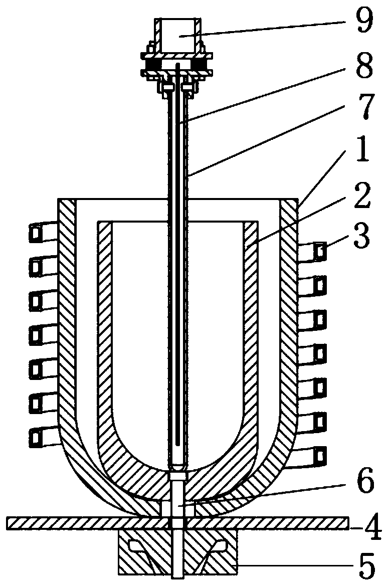
[0086] An exemplary embodiment of the present invention, such as figure 1 As shown, a new type of gas atomization powder making device is provided, which is installed in a gas atomization powder making equipment, including:
[0087] The first crucible 1 is used to prevent the molten alloy from flowing out and damaging the equipment;
[0088] The second crucible 2, the second crucible 2 is arranged inside the first crucible 1, and a filling layer is arranged between the first crucible 1 and the second crucible 2, which is used for alloy melting;
[0089] An induction coil 3, the induction coil sleeve 3 is arranged outside the first crucible 1, and uses the principle of electromagnetic induction to heat and melt the alloy contained in the second crucible 2;
[0090] A thermal insulation component 4, the thermal insulation component 4 is arranged at the bottom of the first crucible 1 for supporting and leveling the first crucible 1, and at the same time can reduce the heat trans...
Embodiment 2
[0151] A specific embodiment of the present invention provides a novel gas atomization powder making device installed in a gas atomization powder making equipment, including:
[0152] The first crucible 1 is used to prevent the molten alloy from flowing out and damaging the equipment;
[0153] The second crucible 2, the second crucible 2 is arranged inside the first crucible 1, and a filling layer is arranged between the first crucible 1 and the second crucible 2, which is used for alloy melting;
[0154] An induction coil 3, the induction coil sleeve 3 is arranged outside the first crucible 1, and uses the principle of electromagnetic induction to heat and melt the alloy contained in the second crucible 2;
[0155] A thermal insulation component 4, the thermal insulation component 4 is arranged at the bottom of the first crucible 1 for supporting and leveling the first crucible 1, and at the same time can reduce the heat transfer from the upper end to the lower end;
[0156]...
Embodiment 3
[0220] A specific embodiment of the present invention, its gas atomization powder making device and assembly method are roughly the same as Embodiment 2, the only difference is:
[0221] The second crucible 2 is "arc" type and made of magnesium oxide.
[0222] Provide a kind of method of novel gas atomization powder making again, use the above-mentioned novel gas atomization powder making device, comprise the following steps:
[0223] Step B0, will GH3536 superalloy parent metal several sections, total weight 5kg is put into the second crucible 2, closes described gas atomization pulverizing equipment;
[0224] Step B1. Carry out vacuuming operation on the gas atomization pulverizing equipment, and stop the vacuuming operation when the internal vacuum degree of the gas atomization pulverizing equipment is 0.78Pa;
[0225] Step B2. Deliver argon to the gas atomization pulverization equipment after vacuuming, control the inflation pressure to 1.5MPa, and stop delivering argon...
PUM
| Property | Measurement | Unit |
|---|---|---|
| Particle size | aaaaa | aaaaa |
| Particle size | aaaaa | aaaaa |
Abstract
Description
Claims
Application Information
 - R&D Engineer
- R&D Manager
- IP Professional
- Industry Leading Data Capabilities
- Powerful AI technology
- Patent DNA Extraction
Browse by: Latest US Patents, China's latest patents, Technical Efficacy Thesaurus, Application Domain, Technology Topic, Popular Technical Reports.
© 2024 PatSnap. All rights reserved.Legal|Privacy policy|Modern Slavery Act Transparency Statement|Sitemap|About US| Contact US: help@patsnap.com