Catalyst ignition stage torque distribution method, system and device

A technology of torque distribution and catalytic converter, applied in transportation and packaging, combustion engines, internal combustion piston engines, etc., can solve the problems of accelerated catalytic converter aging, high CO and HC emissions, battery feeding, etc., to improve fuel economy, The effect of avoiding long heating time and improving purification efficiency

Active Publication Date: 2020-05-26
ZHEJIANG FENGRUI ENGINE CO LTD +1
View PDF9 Cites 10 Cited by
  • Summary
  • Abstract
  • Description
  • Claims
  • Application Information

AI Technical Summary

Problems solved by technology

[0003] The main measures to shorten the ignition of the catalytic converter in traditional cars are: increasing the fuel injection volume and de-ignition angle, thereby increasing the exhaust temperature of the engine, but this method will lead to higher CO and HC emissions during the ignition of the catalytic converter; The auxiliary electric heating device of the catalytic converter requires special modification of the catalytic converter. The installation of a catalytic converter coating temperature sensor and a high-voltage electric heating device not only increases the difficulty of the design and processing of the catalytic converter, but also increases the design of the high-voltage wiring harness of the vehicle. It also increases the R&D and production costs and safety risks of the whole vehicle. In addition, there is a risk of battery power feeding; by optimizing the structural layout of the exhaust pipe, the three-way catalytic converter is closer to the engine exhaust. The air port uses higher temperature exhaust to heat the catalyst, but this method will accelerate the aging of the catalyst and affect the service life of the catalyst

Method used


Image

  • Catalyst ignition stage torque distribution method, system and device
  • Catalyst ignition stage torque distribution method, system and device
  • Catalyst ignition stage torque distribution method, system and device

Examples


Embodiment 1

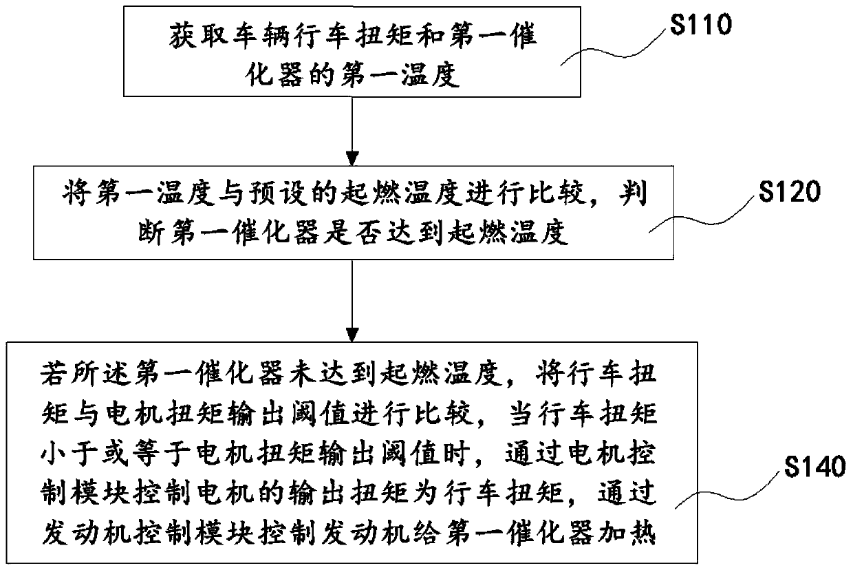
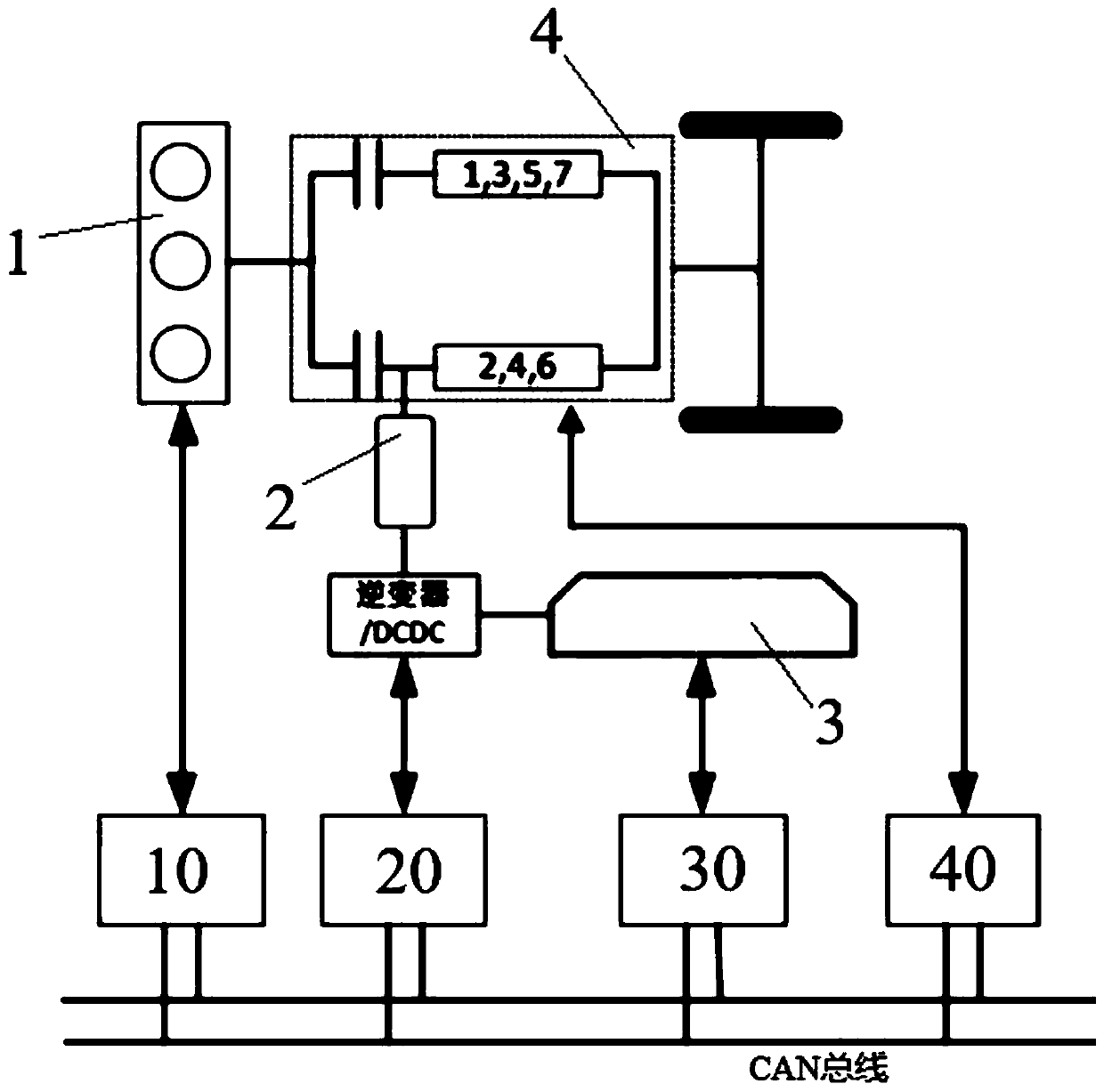
[0061] Please refer to figure 1 with image 3 , the embodiment of this specification provides a torque distribution method for catalytic converter light-off phase, the method is applied to a hybrid vehicle, the hybrid vehicle includes an engine 1, a motor 2, a battery 3 and a transmission clutch 4, the hybrid The vehicle also includes a control system and an exhaust system, the control system includes an engine control module 10 and a motor control module 20, the exhaust system includes an exhaust pipe and a first catalytic converter, and the exhaust pipe is connected to the exhaust pipe of the engine 1 The first catalytic converter is arranged on the exhaust pipe, and the first catalytic converter is connected to the exhaust pipe for purifying CO, HC and NOx in the exhaust gas produced by the engine operation and other harmful gases, the methods include:

[0062] S110: Acquiring the driving demand torque of the vehicle and the first temperature of the first catalytic conver...

Embodiment 2

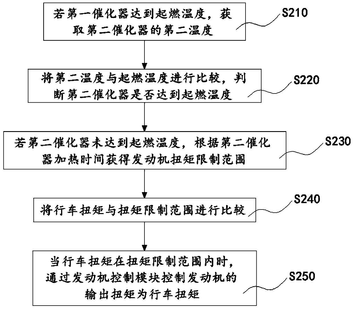
[0077] Please refer to figure 2 with image 3 , the embodiment of this specification provides a torque distribution method in the light-off stage of the catalytic converter. The torque distribution method provided by this embodiment is applied to a hybrid vehicle including a control system and an exhaust system. The difference between this embodiment and Embodiment 1 is: The exhaust system further includes a second catalytic converter, the second catalytic converter is disposed on the exhaust pipe, and the second catalytic converter is disposed on a side of the first catalytic converter away from the exhaust port of the engine. side, that is, the exhaust gas discharged from the engine exhaust port first passes through the first catalytic converter and then passes through the second catalytic converter, so that the unpurified exhaust gas of the first catalytic converter reaches the second catalytic converter through the exhaust pipe. At the catalytic converter, further purifi...

Embodiment 3

[0110] The embodiment of this specification provides a torque distribution system in the light-off stage of the catalytic converter, including:

[0111] a first acquiring unit, configured to acquire the vehicle running demand torque and the first temperature of the first catalytic converter;

[0112] a first judging unit, configured to compare the first temperature with a preset light-off temperature, and judge whether the first catalytic converter has reached the light-off temperature;

[0113] A first control unit, configured to compare the driving demand torque with a motor torque output threshold when the first catalytic converter has not reached the light-off temperature, and when the driving demand torque is less than or equal to the motor torque output threshold , the output torque of the motor is controlled to be the driving demand torque by controlling the motor control module, and the engine is controlled by the engine control module to heat the first catalytic conve...


PUM


Abstract

The invention provides a catalyst ignition stage torque distribution method. The method is used for a hybrid vehicle comprising a control system and an exhaust system. The method comprises the following steps that: a vehicle driving demand torque and the first temperature of a first catalytic converter are acquired, and whether the temperature of the first catalytic converter reaches an ignition temperature or not is judged; and if the temperature of the first catalytic converter does not reach the ignition temperature, the vehicle driving demand torque is compared with a motor torque output threshold value, and when the vehicle driving demand torque is smaller than or equal to the motor torque output threshold value, a motor control module is adopted to control the output torque of the motor to be the vehicle driving demand torque and control an engine to heat the first catalytic converter. On the basis of the method, the invention further provides a system and a device. According tothe method, system and device of the invention, different output torque distribution strategies are designed the engine works under proper working conditions, so that the temperature of the first catalytic converter and the temperature of a second catalytic converter are increased respectively, and meanwhile, the torque output range of the engine is limited; the situation that oil consumption andemission are not facilitated due to multiple transient working conditions of the engine, large load of a refrigerator and the like is avoided; and vehicle fuel economy is improved.

Description

technical field [0001] The invention relates to the field of hybrid vehicle control, in particular to a torque distribution method, system and device in the ignition-off stage of a catalytic converter. Background technique [0002] The three-way catalytic converter is the most important purification device for automobile exhaust emissions. Its conversion efficiency of harmful gases such as CO, HC and NOx produced by the operation of automobile engines is directly related to temperature. In general, the light-off temperature of the catalytic converter refers to the temperature at which the conversion efficiency of the catalytic converter to harmful gases reaches 50%. The conversion efficiency can reach more than 90%. Another study shows that the harmful gas emissions of the engine during its cold phase account for 50% to 80% of the total emissions of the entire emission test cycle. Therefore, shortening the light-off time of the catalytic converter and at the same time cont...

Claims


Application Information

Patent Timeline
Patent Type & Authority Applications(China)
IPC IPC(8): B60W10/06B60W10/08B60W20/15B60W20/16
CPCB60W10/06B60W10/08B60W2510/06B60W2710/0666B60W2710/083B60W20/15B60W20/16Y02T10/40Y02T10/62
Inventor 方小军刘义强金昶明
Owner ZHEJIANG FENGRUI ENGINE CO LTD
Why Eureka
Try Eureka