
Urban surface reflectance remote sensing inversion method

A technology of surface reflectance and remote sensing inversion, which is applied in the field of urban surface reflectance remote sensing inversion, and can solve the problems of insufficient accuracy of urban surface reflectance

Active Publication Date: 2020-05-26
胡德勇 +5
View PDF8 Cites 4 Cited by
  • Summary
  • Abstract
  • Description
  • Claims
  • Application Information

AI Technical Summary

Problems solved by technology

The solar radiation received by the urban area has been redistributed due to the influence of morphological characteristics. The electromagnetic radiation signal received by the entrance pupil of the remote sensing sensor is a comprehensive summary of the underlying surface of the urban area. Therefore, based on the current radiation transfer model, the urban surface reflectance Remote sensing inversion will result in insufficient accuracy of the inversion urban surface reflectance

Method used


Image

  • Urban surface reflectance remote sensing inversion method
  • Urban surface reflectance remote sensing inversion method
  • Urban surface reflectance remote sensing inversion method

Examples


Embodiment 1

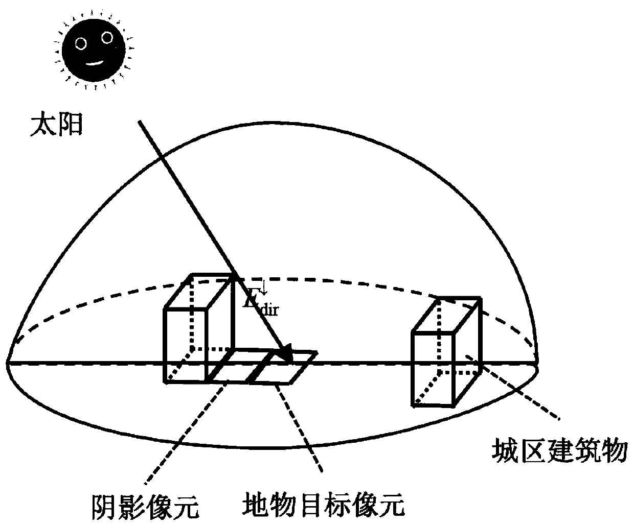
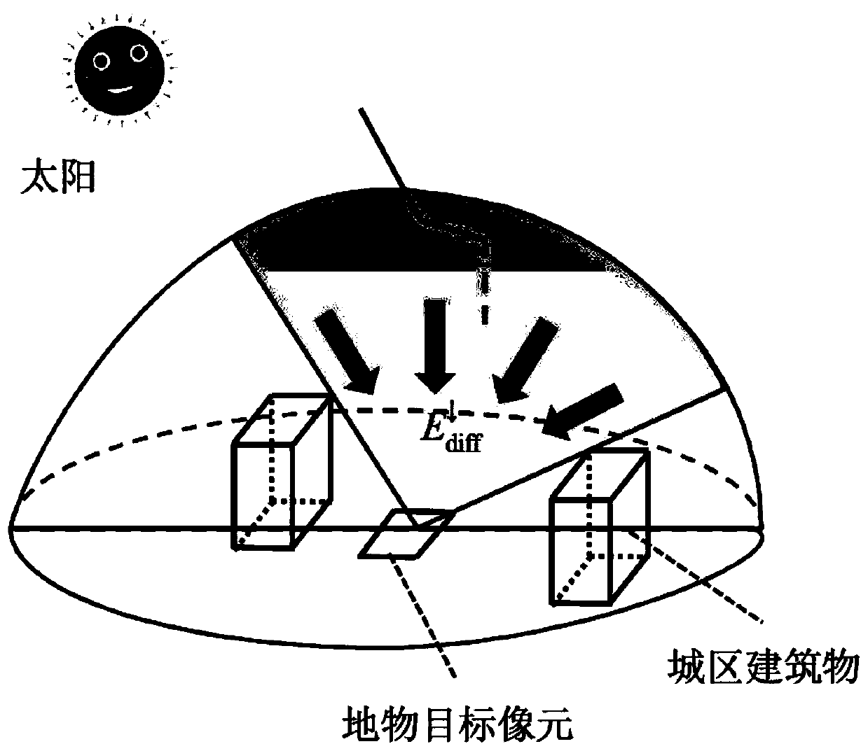
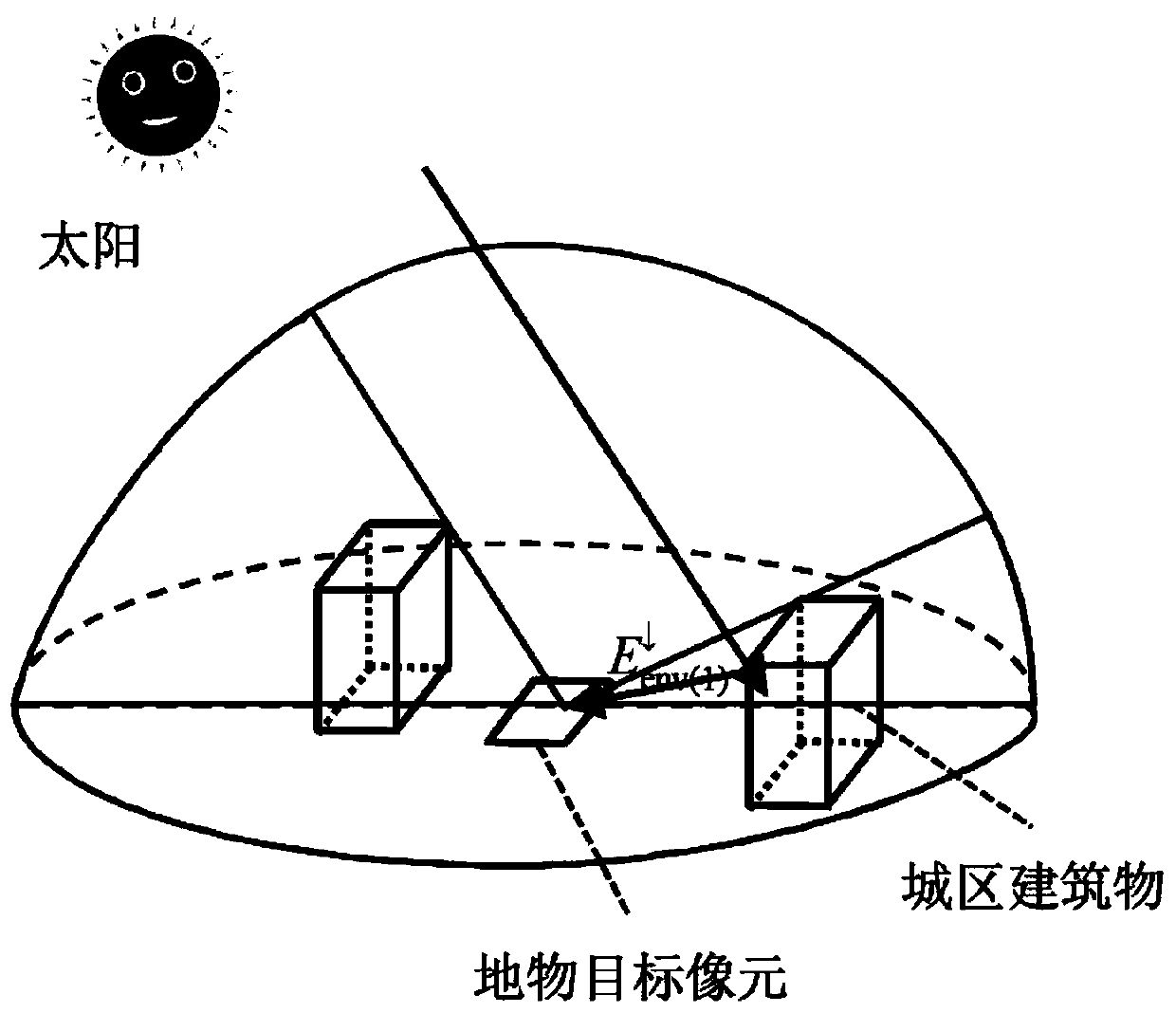
[0062] Such as Figure 1 to Figure 8 As shown, in this embodiment, the inversion method introduces the sky view coefficient, quantifies the morphological and structural characteristics of the underlying surface of the urban area, and analyzes the "urban area-atmosphere" solar short-wave radiation transmission process ( Figure 8 ), and constructed an urban-atmosphere urban solar radiation transfer (Urban Solar Radiative Transfer, USRT) model that takes into account the morphological and structural characteristics of the underlying surface of the urban area. The principle of the USRT model specifically includes the following steps,

[0063] S1. Quantify the total radiation received by the urban surface objects;

[0064] S2, quantify the radiant brightness at the entrance pupil of the sensor;

[0065] S3. Combining steps S1 and S2 to calculate the urban surface reflectance.

[0066] In the present embodiment, because the total radiation received by the urban surface objects a...

Embodiment 2

[0120] In this example, the area around the Bird's Nest is selected as the research area, and the Landsat 8 remote sensing data is taken as an example to list the specific process of inverting the urban surface reflectance based on the USRT model.

[0121] As can be seen from Example 1, when using remote sensing to invert urban surface reflectance, two underlying surface parameters need to be determined: building side reflectance (ρ e ) and sky viewshed coefficient (V). The former set ρ according to the measured value in the study area e value; the latter estimates the V value ( Figure 9 ).

[0122] In addition, the radiance at the entrance pupil of the sensor (L TOA ) is obtained by remote sensing data; other solar radiation and atmospheric parameters are determined by model (6S radiative transfer software package) simulation method, including the solar irradiance at the upper boundary of the atmosphere (E s ), atmosphere-pass radiation (L p ), downlink direct radiation...


PUM


Abstract

The invention discloses an urban surface reflectance remote sensing inversion method, which comprises the following steps of S1, quantifying total radiation received by an urban surface ground objecttarget; S2, quantifying the radiance of the entrance pupil of the sensor; and S3, calculating the surface reflectance of the urban area by combining the step S1 and the step S2. The inversion method has the advantages that the transmission process of solar radiation in an urban area-atmosphere interface is simulated; physical processes such as shielding of direct solar radiation by urban buildings, influence of sky vision field coefficients on sky diffuse radiation and multiple reflection effects of side faces and the earth surface of the buildings are considered, and the model is clear in physical significance and can well represent influence of urban forms and structural features on the solar radiation transmission process.

Description

technical field [0001] The invention relates to the technical field of urban remote sensing, in particular to a remote sensing inversion method for urban surface reflectance. Background technique [0002] In the process of remote sensing inversion of urban surface albedo, the existing radiative transfer models usually regard the land surface as a "flat surface", without considering the morphological and structural characteristics of the underlying surface of the urban area. The solar radiation received by the urban area has been redistributed due to the influence of morphological characteristics. The electromagnetic radiation signal received by the entrance pupil of the remote sensing sensor is a comprehensive summary of the underlying surface of the urban area. Therefore, based on the current radiation transfer model, the urban surface reflectance Remote sensing inversion will result in insufficient accuracy of the inversion of urban surface reflectance. Contents of the i...

Claims


Application Information

Patent Timeline
IPC IPC(8): G01N21/17G01N21/55G01S7/48G01S17/89G06F17/10
CPCG01N21/17G01N21/55G01S17/89G01S7/4802G06F17/10G01N2021/1793
Inventor 胡德勇刘曼晴于琛张亚妮曹诗颂狄宇飞
Owner 胡德勇
Learn More