Detecting device, method for controlling detecting device and circuit for converting charge into voltage

A detection device and voltage conversion technology, which is applied in the direction of measuring device, material capacitance, material analysis through electromagnetic means, etc., can solve the problem of measurement value error and achieve the effect of suppressing error

Pending Publication Date: 2020-05-26
MINEBEA CO LTD
View PDF2 Cites 1 Cited by
  • Summary
  • Abstract
  • Description
  • Claims
  • Application Information

AI Technical Summary

Problems solved by technology

When a leakage current occurs at the capacitance detection pin, the output voltage from the charge amplifier fluctuates, and an error occurs in the measured value.

Method used


Image

  • Detecting device, method for controlling detecting device and circuit for converting charge into voltage
  • Detecting device, method for controlling detecting device and circuit for converting charge into voltage
  • Detecting device, method for controlling detecting device and circuit for converting charge into voltage

Examples


Embodiment Construction

[0039] Hereinafter, modes for implementing the invention will be described with reference to the drawings. In each drawing, the same components are sometimes given the same symbols, and overlapping descriptions are omitted. In addition, in this indication, the humidity when simply describing it as humidity means a relative humidity.

[0040] [Summary structure]

[0041] The configuration of the humidity detection device 10 according to one embodiment of the present invention will be described.

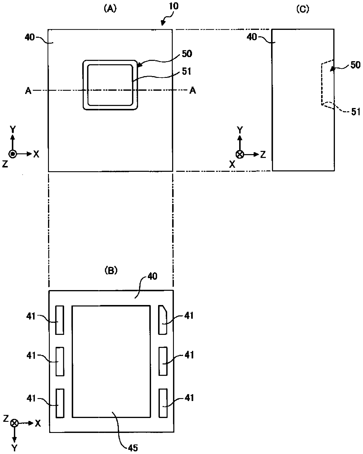
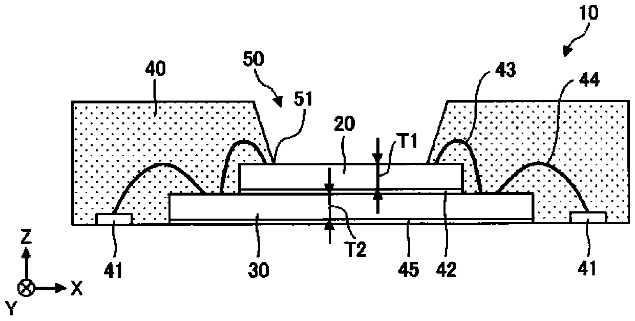
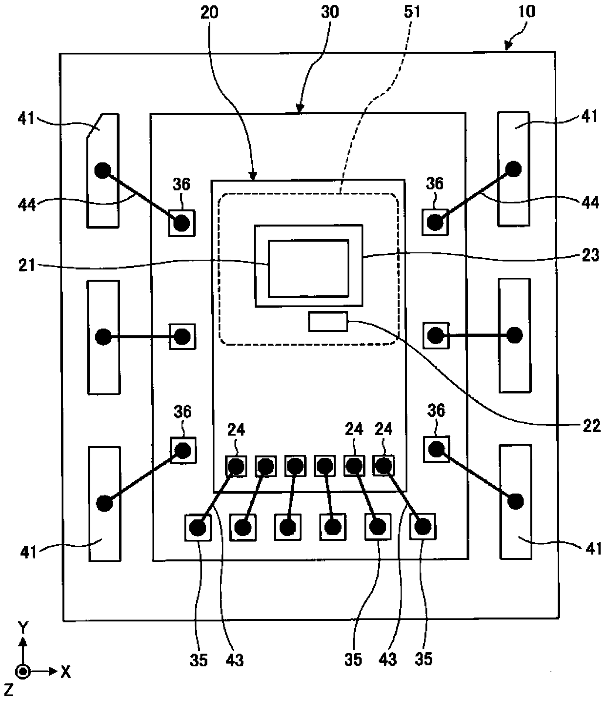
[0042] figure 1 It is a figure which exemplifies the schematic structure of the humidity detection apparatus 10 which concerns on one Embodiment of this invention. figure 1 (A) is a plan view of the humidity detection device 10 viewed from above. figure 1 (B) is a bottom view of the humidity detection device 10 viewed from below. figure 1 (C) is a side view of the humidity detection device 10 viewed from the lateral direction. also, figure 2 is a schematic representation along ...


PUM


Abstract

Provided are a detecting device, a method for controlling the detecting device and a circuit for converting charge into voltage with aim of inhibiting errors of measuring value cased by leak current.The detecting device includes a detecting unit including a first electrode and a second electrode, the first electrode and the second electrode being used as a first capacitor. The detecting device includes a drive unit configured to apply a first drive signal to the first drive terminal such that the first drive signal is alternately inverted between a first period and a second period. The detecting device includes a converting unit configured to convert a charge charged at the signal terminal into a voltage and includes a difference processing unit configured to obtain a difference between the first output voltage and the second output voltage.

Description

technical field [0001] The invention relates to a detection device such as a humidity detection device, a control method of the detection device, and a charge-voltage conversion circuit. Background technique [0002] As a detection device, for example, a humidity detection device includes a capacitive detection device using a moisture-sensitive film formed of a polymer material whose dielectric constant changes according to the amount of absorbed moisture as a dielectric. In this capacitive humidity detection device, a humidity sensitive film is disposed between electrodes, and the humidity (relative humidity) is obtained by measuring the capacitance between the electrodes (for example, refer to Patent Document 1). [0003] In the humidity detection device described in Patent Document 1, a sensor unit whose capacitance changes according to humidity, and a reference unit (reference unit) whose capacitance remains constant regardless of humidity are provided, and the differenc...

Claims


Application Information

Patent Timeline
IPC IPC(8): G01N27/22
CPCG01N27/225G01N27/228G01N27/223G01N27/226
Inventor 井上文裕大塚信也山本康介
Owner MINEBEA CO LTD
Why Eureka
Try Eureka