Manufacturing equipment for laying fiber tape

A technology for manufacturing equipment and fiber belts, applied in the field of laying fiber belts, can solve problems such as high process time, and achieve the effect of shortening the process time

Active Publication Date: 2021-11-30
费尔有限公司
View PDF6 Cites 0 Cited by
  • Summary
  • Abstract
  • Description
  • Claims
  • Application Information

AI Technical Summary

Problems solved by technology

[0004] The devices known from DE 10 2014 101 445 A1 and DE 10 2014 201 060 A1 have the disadvantage that the fiber laying with such configured devices has a high process time

Method used


Image

  • Manufacturing equipment for laying fiber tape
  • Manufacturing equipment for laying fiber tape
  • Manufacturing equipment for laying fiber tape

Examples


Embodiment Construction

[0051] First of all, it must be ensured that in the different described embodiments the same components are provided with the same reference symbols or the same component designations, wherein the disclosure content contained in the entire description can be transferred to reference symbols with the same reference symbols or the same On the same part of the component name. The positional specifications selected in the description, such as top, bottom, side, etc., also refer to the directly described and shown figures, and these positional specifications are transferred to the new position in the event of a position change.

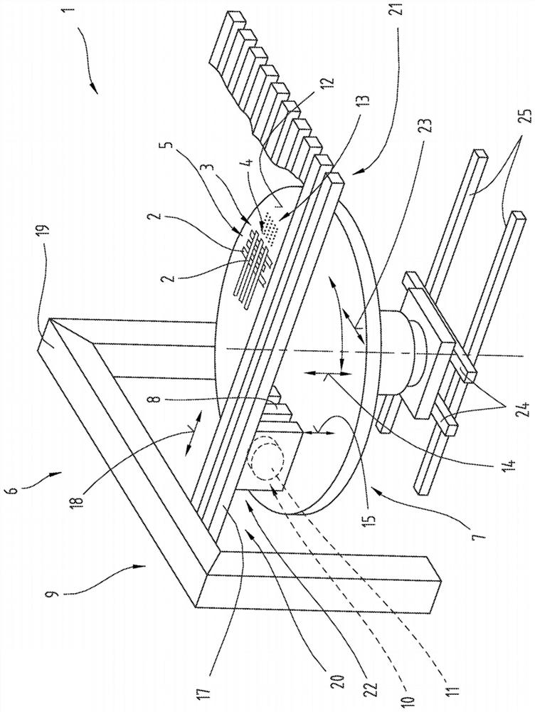
[0052] figure 1 A perspective view of a production device 1 for laying fiber strips 2 is shown. With the aid of the production device 1 , the fiber tape 2 can be laid into a first fiber tape layer 3 . The fiber tape layer 3 can have an outer edge that is contoured and adapted to the respective use by using the individual fiber tapes 2 in the production p...


PUM

PropertyMeasurementUnit
thicknessaaaaaaaaaa

Abstract

The invention relates to a production plant (1) for laying fiber strips (2), said production plant (1) comprising a laying device (6) having an unwinding device receptacle (9) and a side-by-side At least two unwinding devices (8) arranged on the unwinding device receiving part (9), each said unwinding device (8) respectively includes a receiving device (10) for receiving a raw material coil (11) ) and a cutting unit (27) for cutting the fiber tape (2); surface (12), wherein the placement surface (12) of the placement device (7) and the unwinding device (8) of the laying device (6) are relatively movable relative to each other along the laying direction (18), whereby the fiber strip (2 ) can be unwound onto the placement surface (12) in strips. The at least two unwinding devices (8) are each coupled to the unwinding device receptacle (9) of the laying device (6) by means of a linear guide (17), and the at least two unwinding devices can be independent of each other The ground moves relative to the unwinder receptacle (9) in the laying direction (18).

Description

technical field [0001] The invention relates to a production device for laying fiber strips and a method for laying fiber strips. Background technique [0002] A method for forming laminates and an associated tape laying device are known from DE 10 2014 101 445 A1. Here, the strip to be placed, provided with adhesive material and / or matrix material, is transported to the placement device. The supplied tapes are laid down by means of the placement mechanism until a tape structure corresponding to the laminate is obtained consisting of tapes laid side by side and one above the other, wherein the tapes laid side by side define the tape layers of the tape structure. The strip structure is guided onto the ultrasonic excitation means, where the adhesive material and / or the matrix material are continuously plasticized and the individual strip layers are thus connected to each other. [0003] A fiber laying machine for producing fiber laying parts is known from DE 10 2014 201 060 ...

Claims


Application Information

Patent Timeline
Patent Type & Authority Patents(China)
IPC IPC(8): B29C70/38B29C70/22B33Y10/00B33Y30/00B29C64/209B29C64/141B29C64/236B29C31/08
CPCB29C70/386B29C70/545B29C70/38B29C70/228B33Y10/00B33Y30/00B29C64/141B29C64/209B29C64/236B29C70/382B29C70/388B29C2793/0027B29K2101/12
Inventor N·丹宁格
Owner 费尔有限公司
Why Eureka
Try Eureka