Calibration method and calibration system for tool coordinate system of robot

A technology of tool coordinate system and calibration method, which is applied in the field of robot tool coordinate system calibration method and calibration system, can solve the problems of easy occurrence of singular points, high calibration cost, complicated operation, etc., and achieves strong operability and shortens the calibration process. , the effect of reducing the cost of testing

Active Publication Date: 2020-05-29
GREE ELECTRIC APPLIANCES INC
View PDF15 Cites 10 Cited by
  • Summary
  • Abstract
  • Description
  • Claims
  • Application Information

AI Technical Summary

Problems solved by technology

Self-calibration is to rely on the mechanical structure body and control system for calibration. For example, the commonly used method in the industry is the "six-point method", that is, by operating the robot to teach 2 position points and 4 attitude points, the operation is not only complicated and prone to singular points , and the accuracy of the calibrated tool coordinate system is not high
In the auxiliary calibration, due to the different calibration methods, different measurement tools are needed during the calibration process, such as laser trackers and laser feedback devices (such as T-MAC) commonly used in the industry. During the calibration process, it is necessary to operate the robot to calibrate multiple points. Although the measurement system has high accuracy, the calibration process is complicated and the calibration cost is high

Method used


Image

  • Calibration method and calibration system for tool coordinate system of robot
  • Calibration method and calibration system for tool coordinate system of robot
  • Calibration method and calibration system for tool coordinate system of robot

Examples


Embodiment Construction

[0033] Example embodiments will now be described more fully with reference to the accompanying drawings. Example embodiments may, however, be embodied in many forms and should not be construed as limited to the embodiments set forth herein; rather, these embodiments are provided so that this disclosure will be thorough and complete, and will fully convey the concept of example embodiments to those skilled in the art. The same reference numerals denote the same or similar parts in the drawings, and thus their repeated descriptions will be omitted.

[0034] Furthermore, the described features, structures, or characteristics may be combined in any suitable manner in one or more embodiments. In the following description, numerous specific details are provided in order to give a thorough understanding of embodiments of the present disclosure. However, those skilled in the art will appreciate that the technical solutions of the present disclosure may be practiced without one or mo...


PUM


Abstract

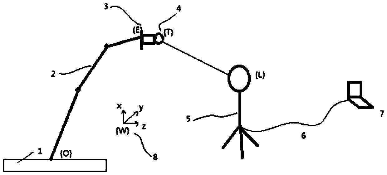
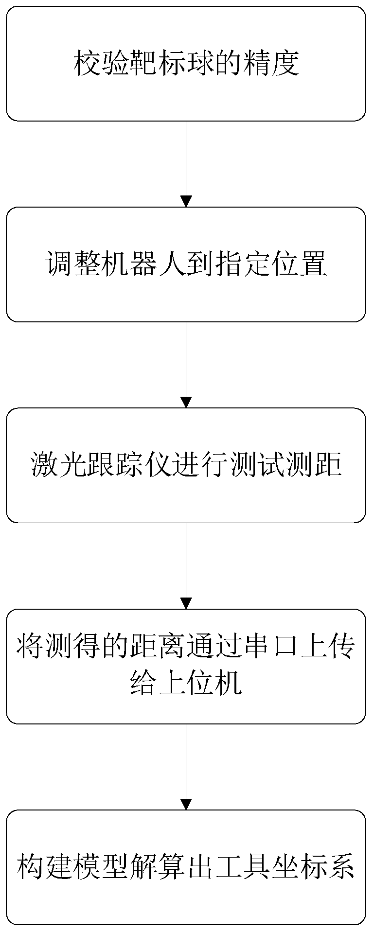
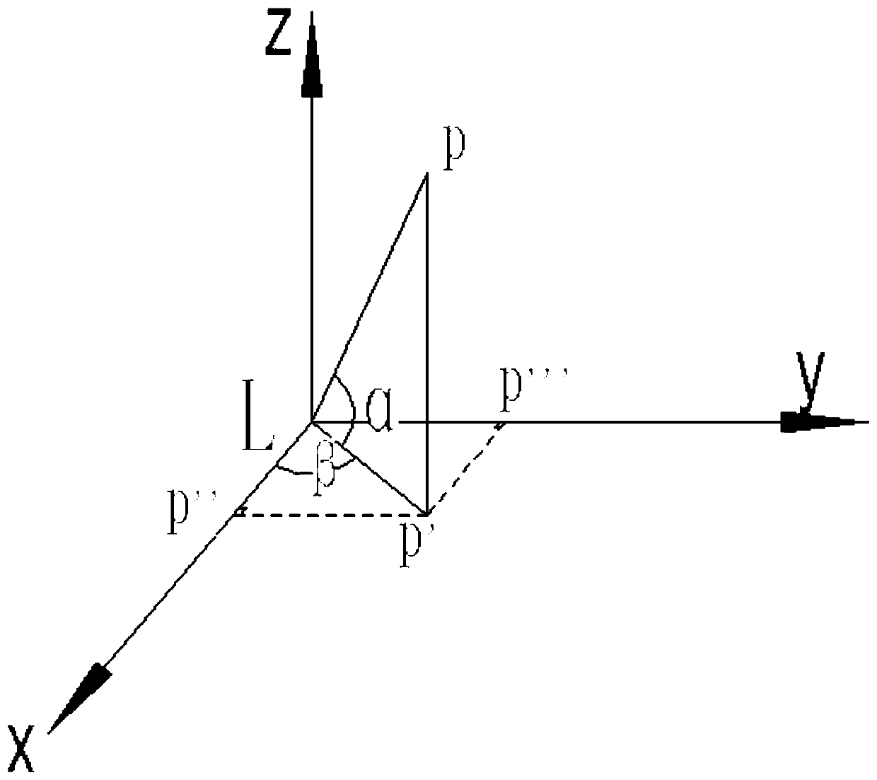
The invention provides a calibration method and calibration system for a tool coordinate system T-xyz of a robot. The calibration method comprises the following steps that a target ball of a laser tracker is mounted on a tool; according to DH parameters of the robot, a base coordinate system O-xyz of the robot and the tool coordinate system T-xyz are established, and the tool coordinate system T-xyz is established with a preset position of the target ball as the coordinate center, wherein the tool coordinate system T-xyz is consistent with a coordinate system E-xyz of the joint at the tail endof the robot in direction; the robot is moved to any non-singular point, and the angles of joints are recorded; and a relative distance H between the preset position of the target ball mounted on thetool and the laser tracker is measured through the laser tracker, and the tool coordinate system T-xyz is calibrated according to the data. According to the calibration method and calibration systemfor the tool coordinate system T-xyz of the robot, the test cost is reduced under the condition that the measurement precision is not reduced; according to the calibration method, the coordinate system of a tool can be solved theoretically by calibrating only one point, so that the calibration process is shortened; and according to the calibration method, the laser tracker and a software system are used, and a closed-loop system among the coordinate systems is formed by building a mechanical model and actual measurement data, so that the calibration method is convenient and rapid and high in operability.

Description

technical field [0001] The invention belongs to the field of robots, and in particular relates to a calibration method and a calibration system of a robot tool coordinate system. Background technique [0002] Robots such as six-axis robots are widely used in various fields due to their convenient operation and flexible use. In different application scenarios, different tools need to be replaced, and the tool coordinate system needs to be re-established, that is, the tool coordinate system needs to be recalibrated. [0003] The current mature calibration methods are divided into two categories, self-calibration and auxiliary calibration. Self-calibration is to rely on the mechanical structure body and control system for calibration. For example, the commonly used method in the industry is the "six-point method", that is, by operating the robot to teach 2 position points and 4 attitude points, the operation is not only complicated and prone to singular points , and the accur...

Claims


Application Information

Patent Timeline
Patent Type & Authority Applications(China)
IPC IPC(8): B25J9/02B25J9/16B25J19/00G01B11/00
CPCB25J9/023B25J9/1692B25J19/0095G01B11/002
Inventor 赵航刘旭魏佳欣王长恺胡飞鹏应坤
Owner GREE ELECTRIC APPLIANCES INC
Why Eureka
Try Eureka