
A shadowless deflectable LED lighting source for surgery

A technology for LED lighting and surgery, which is applied in the field of shadowless and deflectable LED lighting sources for surgery, which can solve the problems of unsuitable miniaturized use occasions, large volume and weight of LED lamp groups, and large volume of deflection mechanisms, etc., to improve lighting. Area-wide, compact, high-resolution effects

Active Publication Date: 2021-12-28
山东曲阜康尔健医疗科技有限公司
View PDF7 Cites 0 Cited by
  • Summary
  • Abstract
  • Description
  • Claims
  • Application Information

AI Technical Summary

Problems solved by technology

[0003] In the currently known LED light source structures, the basic light-emitting units are all fixed structures. However, in many cases in the actual use of LED light sources, the lighting range of the light source is required to be wider or the lighting range is variable; The unit is a fixed structure, so that to achieve the purpose of variable lighting range, the entire LED light source needs to be a movable structure. Such an overall mobile structure has a large rotational inertia due to the large volume and weight of the entire LED light group. The deflection response is poor, and the volume of the entire deflection mechanism is correspondingly large, which cannot adapt to various increasingly miniaturized use occasions today.

Method used


Image

  • A shadowless deflectable LED lighting source for surgery
  • A shadowless deflectable LED lighting source for surgery
  • A shadowless deflectable LED lighting source for surgery

Examples


Embodiment Construction

[0023] DRAWINGS Examples and embodiments of the present invention will be further described in detail, the scope of the present invention is not limited thereto.

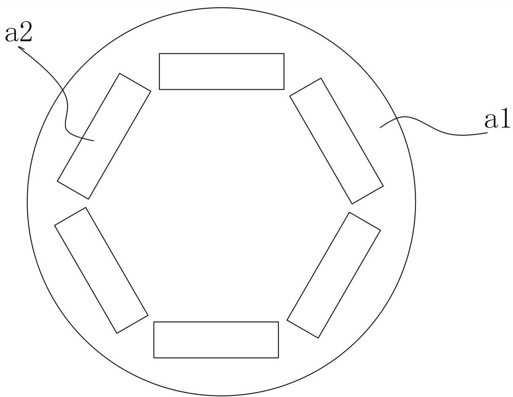
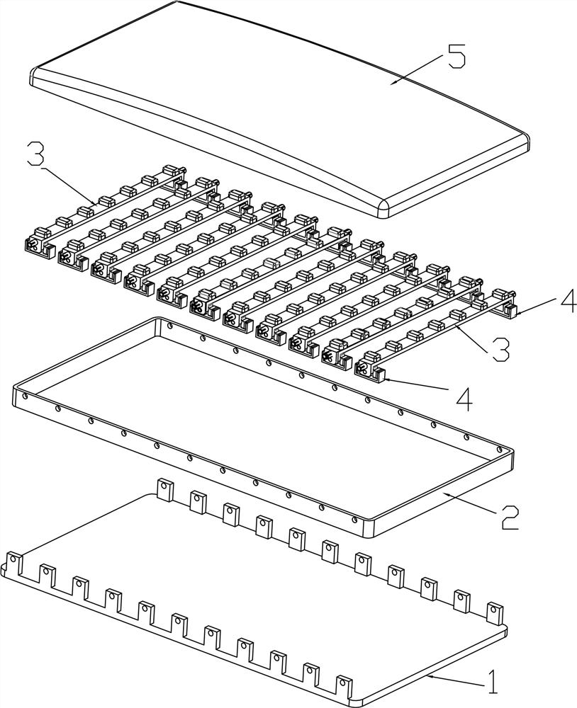
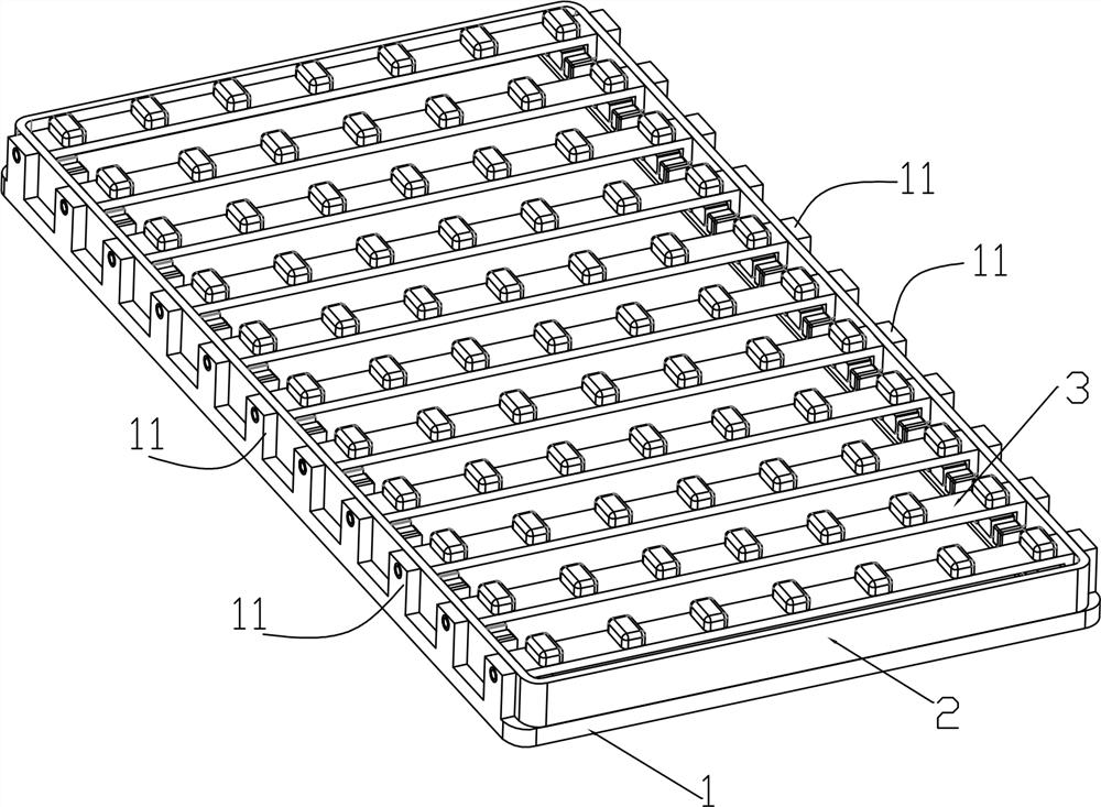
[0024] like Figure 1 to 5 As shown in A deflectable surgical shadowless LED lamp embodiment of the present embodiment,

[0025] Including optical disc can be lifted opposing a1, a1 of the set on the optical disk has a plurality of deflectable about a central illumination unit a2.

[0026] Each deflectable a2 lighting unit comprises a base 1, a mask mounting frame 2, a plurality of flip lamps 1 spaced along the longitudinal direction of the base unit 3, a plurality of magnetic deflection control unit 4 and a light transmissive mask 5;

[0027] Side edges of the base 1 corresponding to each set of cells reversing lamp along the longitudinal direction 3 are provided upright 11, each of the posts 11 has a through hole;

[0028] Mounting the mask frame 2 is provided on the base 1, and a width smaller than the base 1;

[0029...


PUM


Abstract

The invention discloses a shadowless and deflectable LED lighting source for surgery, which comprises a base, a mask mounting frame, a turning light group unit, a magnetic deflection control unit and a light-transmitting mask. The width of the mask mounting frame is smaller than the width of the base, and the turning light group is The unit includes a deflection frame and a plurality of light-emitting chips arranged at intervals on the deflection frame. Permanent magnets are respectively fixed on the inner sides of the two ends of the deflection frame, and a rotating shaft protrudes from the outer sides of the two ends of the deflection frame, and the rotating shaft is installed through the mask outward. The back of the frame is rotatably connected in the through hole of the column, the rotating shaft is embedded with a conductive electrode, the inner top surface of the deflection frame is provided with a conductive layer, and the conductive layer is electrically connected to the conductive electrode; the magnetic deflection control unit includes a bracket, and the two sides of the bracket Electromagnets are respectively fixed at the ends; the present invention can individually adjust the deflection angle of each flip light group unit in the LED light source, can realize multi-directional lighting, increase the width of the lighting area, and can also control the light direction to realize targeted lighting, greatly reducing The rotational inertia makes the deflection correspondingly fast.

Description

Technical field [0001] The present invention relates to a surgical shadowless deflectable LED lamp. Background technique [0002] LED light source due to its volume, brightness, and advantages of controllability of lifetime gradually replace traditional light sources, more and more widely used in all aspects of life. [0003] LED light source currently known configuration, the basic light emitting unit are fixed structure, but in practice the use of LED light sources in many cases, a wider range of illumination light source is required or variable illumination range; due to the current light-emitting LED light source unit is a fixed structure, such that the illumination range of the variable to be achieved it is necessary that the entire purpose of the LED light source is a movable structure, such structure integrally moved since the LED lamps are large size and weight, a large rotational inertia, poor response to deflection, the volume of the entire deflection mechanism also cor...

Claims


Application Information

Patent Timeline
Patent Type & Authority Patents(China)
IPC IPC(8): F21S8/06F21V21/15F21V14/02F21W131/205F21Y115/10
CPCF21S8/06F21V21/15F21V14/02F21W2131/205F21Y2115/10
Inventor 黄加伟
Owner 山东曲阜康尔健医疗科技有限公司
Learn More