Dustproof heat dissipation mechanism and multifunctional high-voltage power distribution cabinet for new energy automobile

A technology of heat dissipation mechanism and dustproof, applied in substation/distribution device casing, electrical components, substation/switch layout details, etc., can solve the problems of poor cooling effect and easy blocking of dustproof meshes, so as to avoid blockage. , Good dustproof effect

Inactive Publication Date: 2020-05-29
苏州本末智能科技有限公司
View PDF11 Cites 18 Cited by
  • Summary
  • Abstract
  • Description
  • Claims
  • Application Information

AI Technical Summary

Problems solved by technology

[0004] During the use of the high-voltage power distribution cabinet of new energy vehicles, due to the high-speed operation of the car, the heat inside the power distribution cabinet will also rise, so heat dissipation is required. The air inlet direction of the fan

Method used


Image

  • Dustproof heat dissipation mechanism and multifunctional high-voltage power distribution cabinet for new energy automobile
  • Dustproof heat dissipation mechanism and multifunctional high-voltage power distribution cabinet for new energy automobile
  • Dustproof heat dissipation mechanism and multifunctional high-voltage power distribution cabinet for new energy automobile

Examples


Embodiment 1

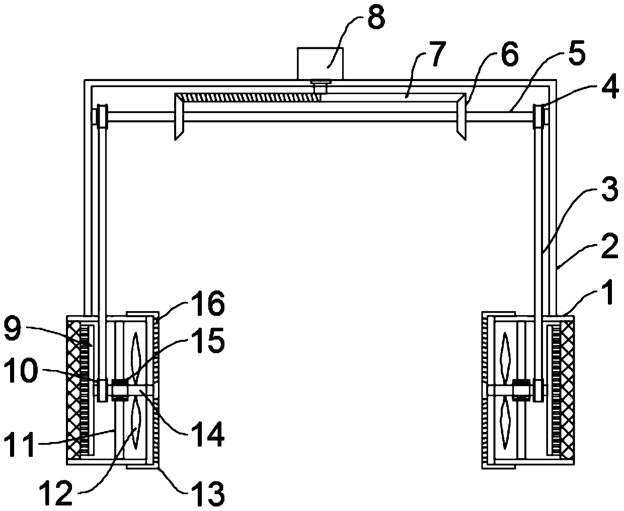
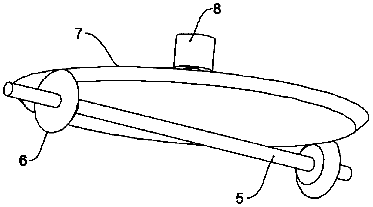
[0021] see Figure 1-2 , in an embodiment of the present invention, a dust-proof heat dissipation mechanism, including a portal frame 2, an installation cylinder 1 and fan blades 12, the installation cylinder 1 is installed on both sides of the bottom of the portal frame 2, and the installation cylinder 1 is installed There are fan blades 12, a motor 8 is installed in the middle of the portal frame 2 top, a semi-conical gear 7 is installed on the output shaft of the motor 8, and a rotating shaft 5 is installed below the semi-conical gear 7 on the portal frame 2, and the rotating shaft 5 passes through the bearing and Portal frame 2 is rotationally connected, bevel gear 6 is installed on both sides of half bevel gear 7 on the rotating shaft 5, the diameter of half bevel gear 7 is at least 10 times of the diameter of bevel gear 6, bevel gear 6 meshes with half bevel gear 7, The outer side of the installation cylinder 1 is equipped with a dust-proof net, the installation cylinder...

Embodiment 2

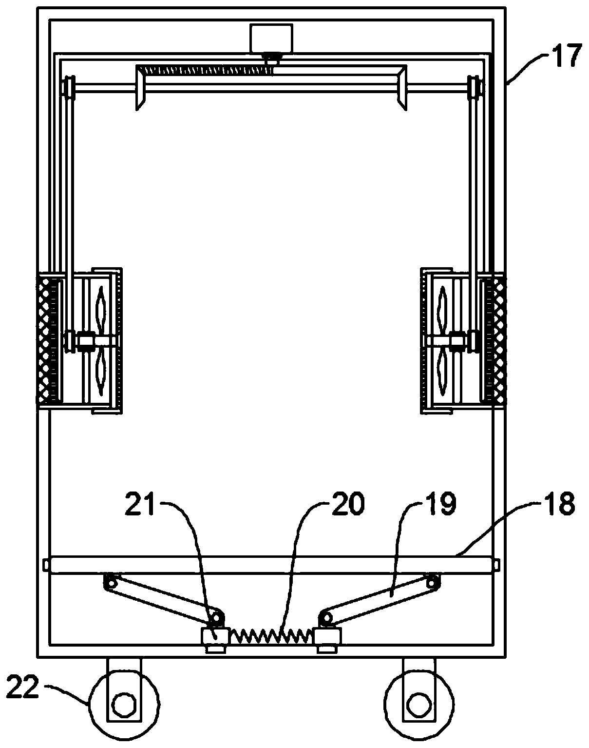
[0023] see image 3 , a multifunctional high-voltage power distribution cabinet for new energy vehicles, including the dust-proof heat dissipation mechanism described in Embodiment 1, and also includes a cabinet body 17 and a shock absorbing device, and the dust-proof heat dissipation mechanism is installed on the cabinet body 17 Inside, the four corners of the bottom of the cabinet body 17 are equipped with rollers 22. The rollers 22 are self-locking rollers to facilitate the movement of the device. Plate 18, connecting rod 19, movable block 21 and damping spring 20, the first slide block is fixed on both sides of described mounting plate 18, and the first slide block is slidingly connected with the inner wall of cabinet body 17, and both sides of mounting plate 18 bottom are all hinged There is a connecting rod 19, the other end of the connecting rod 19 is inclined towards the middle part of the mounting plate 18 and is hinged with a movable block 21, the bottom of the movab...


PUM


Abstract

The invention discloses a dustproof heat dissipation mechanism. The mechanism comprises an n-shaped frame, mounting cylinders and fan blades; the mounting cylinders are mounted on the two sides of thebottom of the n-shaped frame correspondingly; a motor is mounted in the middle of the top of the n-shaped frame; a semi-conical gear is mounted on the output shaft of the motor; a rotating shaft below the semi-conical gear is arranged on the n-shaped frame; bevel gears located on the two sides of the semi-conical gear are mounted on the rotating shaft; the bevel gears are meshed with the semi-conical gear; mounting shafts are arranged in the mounting cylinders; the fan blades are mounted on the mounting shafts. The dustproof heat dissipation mechanism of the invention is provided with the motor, the semi-conical gear, the bevel gears, a first belt pulley, a belt, a second belt pulley and the mounting shafts; when the fan blades rotate forwardly, air is continuously pumped into a power distribution cabinet through dust screens to perform air cooling; the fan blades rotate reversely, the air in the power distribution cabinet is pumped out, dust in the dust screens is blown to the outside of the power distribution cabinet; and therefore, the dust is prevented from entering the power distribution cabinet, a good dustproof effect is achieved, and the dust screens can be prevented frombeing blocked by more and more dust.

Description

technical field [0001] The invention relates to the technical field of automobiles, in particular to a dust-proof heat dissipation mechanism and a multifunctional high-voltage power distribution cabinet for new energy vehicles. Background technique [0002] New energy vehicles refer to the use of unconventional vehicle fuels as power sources or the use of conventional vehicle fuels, the use of new vehicle power devices, and the comprehensive vehicle power control and advanced technology in driving, forming advanced technical principles and new technologies. , The new structure of the car. [0003] Power distribution cabinets (boxes) are divided into power distribution cabinets (boxes), lighting distribution cabinets (boxes), and metering cabinets (boxes), which are the final equipment of the power distribution system. The power distribution cabinet is a general term for the motor control center. The power distribution cabinet is used in the occasions where the load is rela...

Claims


Application Information

Patent Timeline
IPC IPC(8): H02B1/30H02B1/56H02B1/28H02B1/54H02B1/52
CPCH02B1/28H02B1/30H02B1/52H02B1/54H02B1/565
Inventor 刘丽娜
Owner 苏州本末智能科技有限公司
Why Eureka
Try Eureka