Peritoneal dialysis sterile connecting device

A technology for aseptic connection and peritoneal dialysis, which is applied in peritoneal dialysis, dialysis systems, catheters, etc., and can solve the problem of pre-contamination of peritoneal dialysis fluid tube head, easy contamination of peritoneal dialysis aseptic connection operation by foreign objects, and dialysate contamination, etc. question

Pending Publication Date: 2020-06-02
PEKING UNIV SHENZHEN HOSPITAL
View PDF0 Cites 3 Cited by
  • Summary
  • Abstract
  • Description
  • Claims
  • Application Information

AI Technical Summary

Problems solved by technology

[0004] For the above operations, it needs to be carried out under sterile conditions, otherwise, when the connector of the external short tube of the iodophor cap is removed and/or the peritoneal dialysis fluid tube head of the cap is contaminated, it is easy to cause The dialysate flowing through it is contaminated, which makes it easy to cause peritonitis and other complications to the patient and bring danger to the patient's life
[0005] The common disadvantages of the above-mentioned patients or their family members' home operations are: the patient or the patient's family members are not professionals, and their understanding of aseptic awareness is not comprehensive enough. Use their right hand to cooperate with their left hand to connect the end of the external short tube held by the left hand. When the iodophor cap outside the head is r

Method used


Image

  • Peritoneal dialysis sterile connecting device
  • Peritoneal dialysis sterile connecting device
  • Peritoneal dialysis sterile connecting device

Examples


Embodiment Construction

[0050] The technical solution of the present invention will be described in detail below in conjunction with the accompanying drawings and specific embodiments, so as to understand the essence of the present invention more clearly and intuitively.

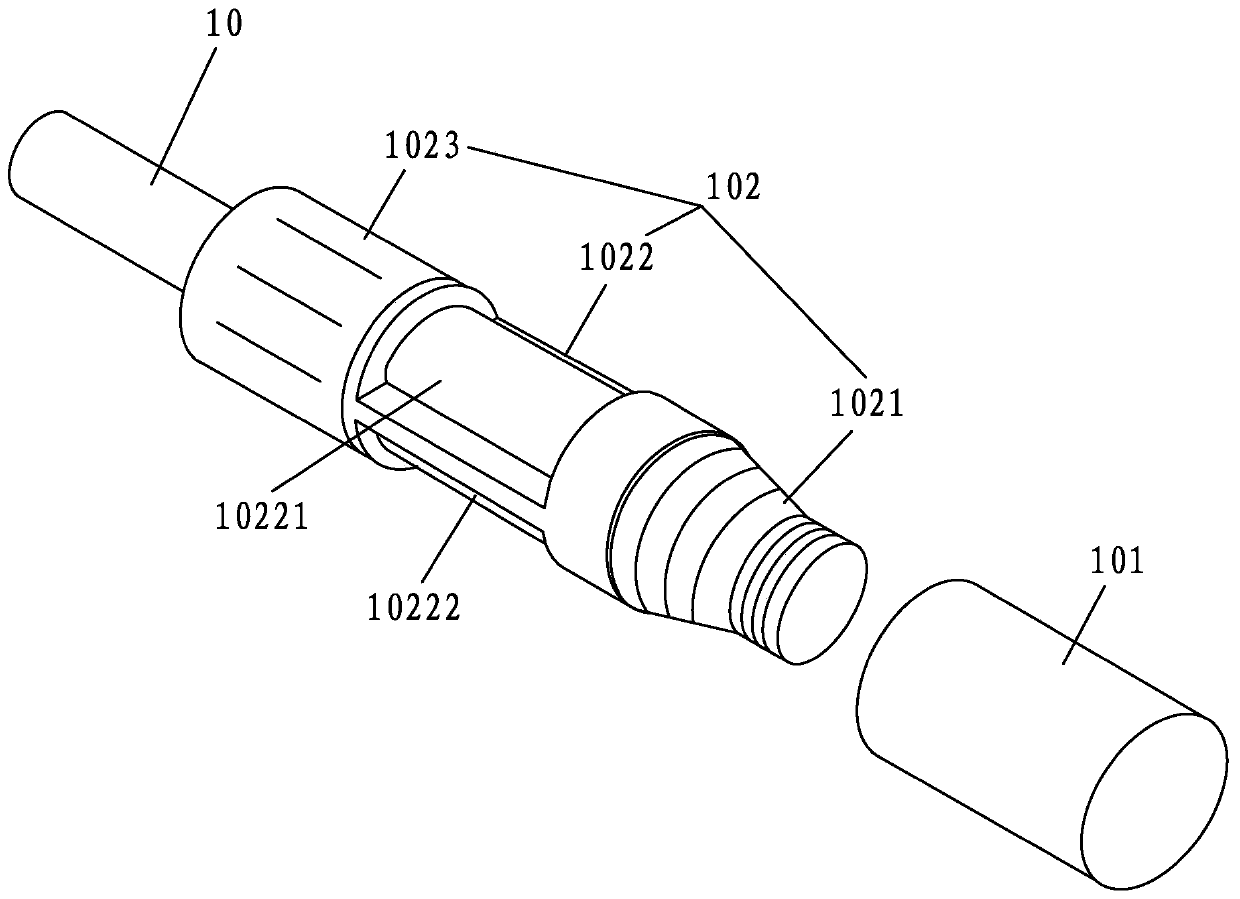
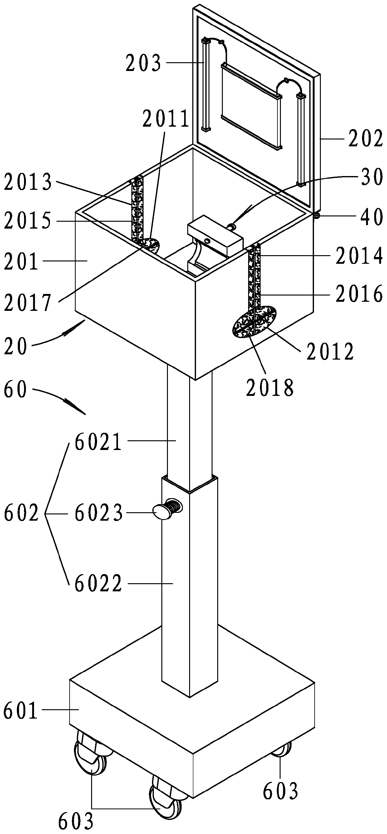
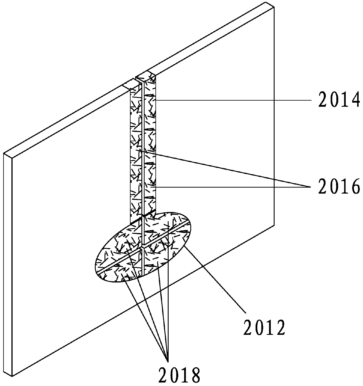
[0051] figure 1 is a partial exploded view of the external short pipe in the prior art; figure 2 It is a schematic diagram of the overall structure of the peritoneal dialysis aseptic connection device of the present invention when the box cover is opened; image 3 It is a schematic diagram of the overall structure of the clamping seat when the upper fixing seat and the lower fixing seat are opened in the embodiment of the present invention;

[0052] to combine figure 1 , figure 2 and image 3 shown;

[0053] A peritoneal dialysis aseptic connection device provided by the present invention is mainly used to connect the peritoneal dialysis fluid pipe and the external short pipe 10 during specific implementation.

[0054] The ...


PUM


Abstract

The present invention discloses a peritoneal dialysis sterile connecting device. The peritoneal dialysis sterile connecting device comprises a sterile connection operation box and a clamping and fixing seat for clamping and fixing a cylindrical transition part of a connector of an external short pipe; and the sterile connection operation box is made of transparent materials and the clamping and fixing seat is fixedly arranged in the sterile connection operation box. The sterile connection operation box provides a sterile operation space, so that a peritoneal dialysis solution pipe and the external short pipe can be accommodated in the sterile connection operation box for connection, so that the peritoneal dialysis solution pipe and the external short pipe are both difficult to pollute by touching of foreign objects or adhering of outside dust, etc., the clamping and fixing seat is suitable for clamping and fixing the cylindrical transition part of the connector of the external short pipe and can play an effect of a third hand to help pull out an iodophor cap at a threaded connection part of the connector of the external short pipe and help connect the external short pipe and the peritoneal dialysis solution pipe, so that compared with traditional operation methods, the manner adopted by the peritoneal dialysis sterile connecting device does not easily cause problems that the connector of the external short pipe is polluted in advance and a pipe head of the peritoneal dialysis solution pipe is polluted in advance, and therefore, the peritoneal dialysis sterile connecting device is good in pollution prevention effect when in use.

Description

technical field [0001] The invention relates to the technical field of medical equipment, in particular to a peritoneal dialysis aseptic connecting device. Background technique [0002] Peritoneal dialysis (PD) is a dialysis method that uses the body's own peritoneum as the dialysis membrane. The dialysate infused into the peritoneal cavity exchanges solutes and water with the plasma components in the capillaries on the other side of the peritoneum, removes the metabolites and excess water retained in the body, and at the same time replenishes the body’s essential substances through the dialysate. Through continuous renewal of peritoneal dialysis fluid, the purpose of renal replacement or supportive treatment can be achieved. [0003] In the existing life, many patients often perform peritoneal dialysis at home. When the patient needs peritoneal dialysis, it is necessary to connect the peritoneal dialysis fluid tube and the external short tube. Connect the end of the exter...

Claims


Application Information

Patent Timeline
IPC IPC(8): A61M1/28
CPCA61M1/28A61M1/285A61M2202/0413A61M2202/0021
Inventor 何艳
Owner PEKING UNIV SHENZHEN HOSPITAL
Why Eureka
Try Eureka