
Laser welding machine with laser head provided with protection assembly

A technology of laser welding machine and laser head, which is applied in the direction of laser welding equipment, welding equipment, metal processing equipment, etc. It can solve the problems of fire, flame generation, and no protective device, etc., and achieve the effect of preventing rotation and convenient cleaning

Inactive Publication Date: 2020-06-02
ANHUI CHUNGU 3D PRINTING INTELLIGENT EQUIP IND TECH RES INST CO LTD
View PDF6 Cites 6 Cited by
  • Summary
  • Abstract
  • Description
  • Claims
  • Application Information

AI Technical Summary

Problems solved by technology

[0004] The object of the present invention is to provide a laser welding machine with a protective assembly for the laser head, to solve the above-mentioned background technology, the laser head on the current laser welding machine is exposed to the outside, there is no protective device around, and the surrounding of the laser head when welding Impurities such as flames and welding slag will be generated, and the impurities will splash everywhere. Due to the high temperature of the impurities, it is easy to scald the staff when splashed out, and may cause fire problems

Method used


Image

  • Laser welding machine with laser head provided with protection assembly
  • Laser welding machine with laser head provided with protection assembly
  • Laser welding machine with laser head provided with protection assembly

Examples


Embodiment Construction

[0022] The following will clearly and completely describe the technical solutions in the embodiments of the present invention with reference to the accompanying drawings in the embodiments of the present invention. Obviously, the described embodiments are only some, not all, embodiments of the present invention. The specific embodiments described here are only used to explain the present invention, not to limit the present invention. Based on the embodiments of the present invention, all other embodiments obtained by persons of ordinary skill in the art without making creative efforts belong to the protection scope of the present invention.

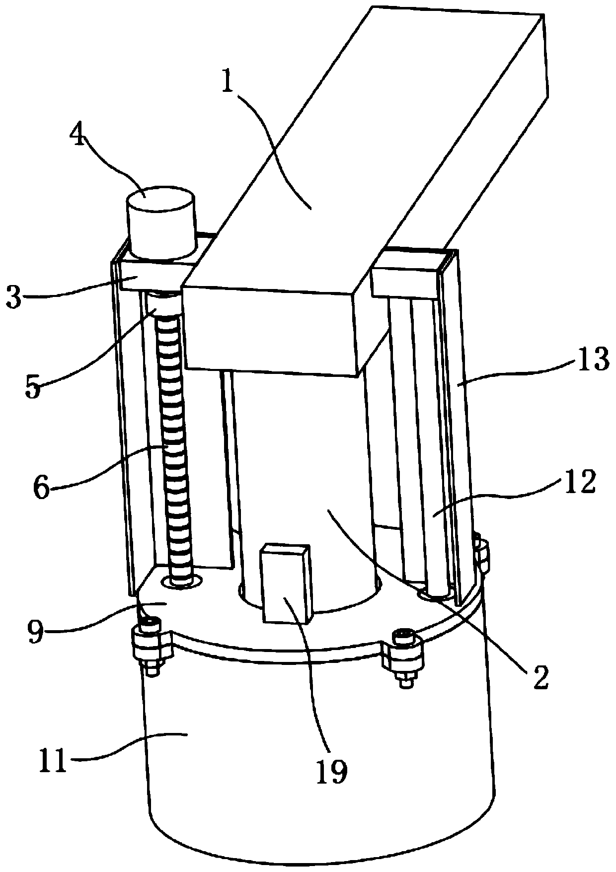
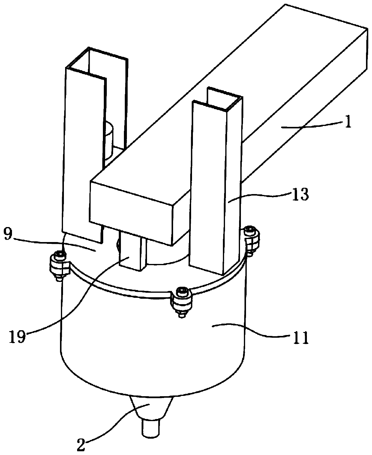
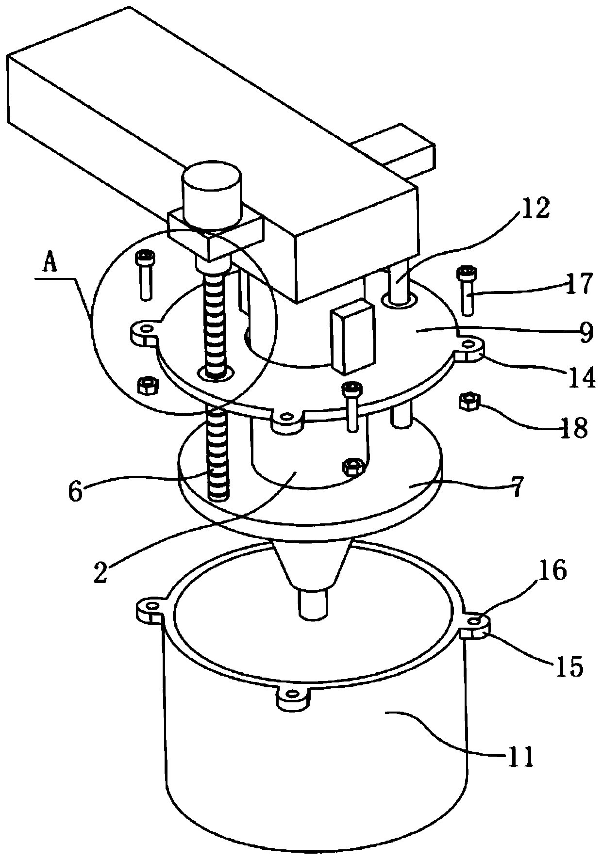
[0023] Such as Figure 1-5 As shown, the present invention provides a laser welding machine with a laser head with a protective assembly, including a cross arm 1, the cross arm 1 is installed on the laser welding machine, the front end of the cross arm 1 is equipped with a laser head 2, and the front end of the cross arm 1 The first fixe...


PUM


Abstract

The invention discloses a laser welding machine with a laser head provided with a protection assembly. The laser welding machine comprises a transverse arm, and the transverse arm is installed on thelaser welding machine. The laser head is installed at the front end of the transverse arm. A first fixing block is welded to the front end of the transverse arm, and a servo motor is fixed to the upper end of the first fixing block. The end portion of an output shaft of the servo motor is fixedly provided with a screw rod through a coupler, and the lower end, away from the servo motor, of the screw rod is rotationally connected with a supporting disc through a bearing. The supporting disc is fixed to the lower side of the laser head, and a transmission nut is connected to the screw rod in a threaded transmission manner. A moving disc is inlaid in the outer side of the transmission nut, and a through hole is formed in the center position of the moving disc. The laser head penetrates the moving disc through the through hole, and a protection cover is arranged on the outer side of the lower end face of the moving disc. The laser head is located in the center position of the interior of the protection cover, and a guide mechanism is arranged on the side, away from the screw rod, of the moving disc. The periphery is isolated and protected when the laser head works, and safety is high.

Description

technical field [0001] The invention belongs to the technical field of welding machine accessories, and in particular relates to a laser welding machine with a protective assembly on the laser head. Background technique [0002] Laser welding is an efficient and precise welding method that uses a high-energy-density laser beam as a heat source. Laser welding is one of the important aspects of the application of laser material processing technology. It is mainly used for welding thin-walled materials and low-speed welding. The welding process is of heat conduction type, that is, the laser radiation heats the surface of the workpiece, and the surface heat diffuses to the inside through heat conduction. By controlling the parameters such as the width, energy, peak power and repetition frequency of the laser pulse, the The workpiece melts to form a specific molten pool. [0003] At present, laser welding is mostly carried out by laser welding machine. The welding head of laser...

Claims


Application Information

Patent Timeline
Patent Type & Authority Applications(China)
IPC IPC(8): B23K26/70B23K26/21
CPCB23K26/21B23K26/702
Inventor 吴志华黄仲佳周晓宏罗贤国张勇孙文明赵薇郑兰斌王心生杨军李思文宗泽周翔吕晨艾晓蕾
Owner ANHUI CHUNGU 3D PRINTING INTELLIGENT EQUIP IND TECH RES INST CO LTD
Learn More