Workpiece spacing adjusting device

A technology for adjusting devices and spacing, applied in metal processing, manufacturing tools, metal processing equipment, etc., can solve the problems of high manufacturing and maintenance costs, complex mechanical structure, etc., and achieve low manufacturing and maintenance costs, simple structure, and high precision Effect

Inactive Publication Date: 2020-06-02
HANYU GRP CO LTD
View PDF6 Cites 1 Cited by
  • Summary
  • Abstract
  • Description
  • Claims
  • Application Information

AI Technical Summary

Problems solved by technology

In order to change the spacing, servo motors are commonly used to drive multiple ball screws, or multiple cylinders are used to individually change the spacing between each workpiece. The mechanical structure is complex and the manufacturing and maintenance costs are high.

Method used


Image

  • Workpiece spacing adjusting device
  • Workpiece spacing adjusting device
  • Workpiece spacing adjusting device

Examples


Embodiment 1

[0045] Embodiment 1 The workpiece spacing adjustment device completes a work cycle according to the following 9 steps, and the process is as follows:

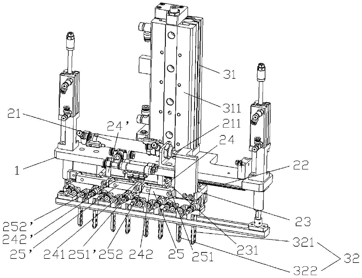
[0046] Such as figure 1 , the device is in the initial state, the piston rods of the cylinders 21, 31 are in the limit position of retraction, the driving slider 23 and the driven slider 24, and the driven sliders 24, 24' are close to each other and are in the initial position, The gripper 32 is held high with the device as a whole. The movable end 252,252' of each connecting rod 25,25' is in contact with the inner surface of the left end of the movable card slot 242,242' of the connected driven slider 24,24';

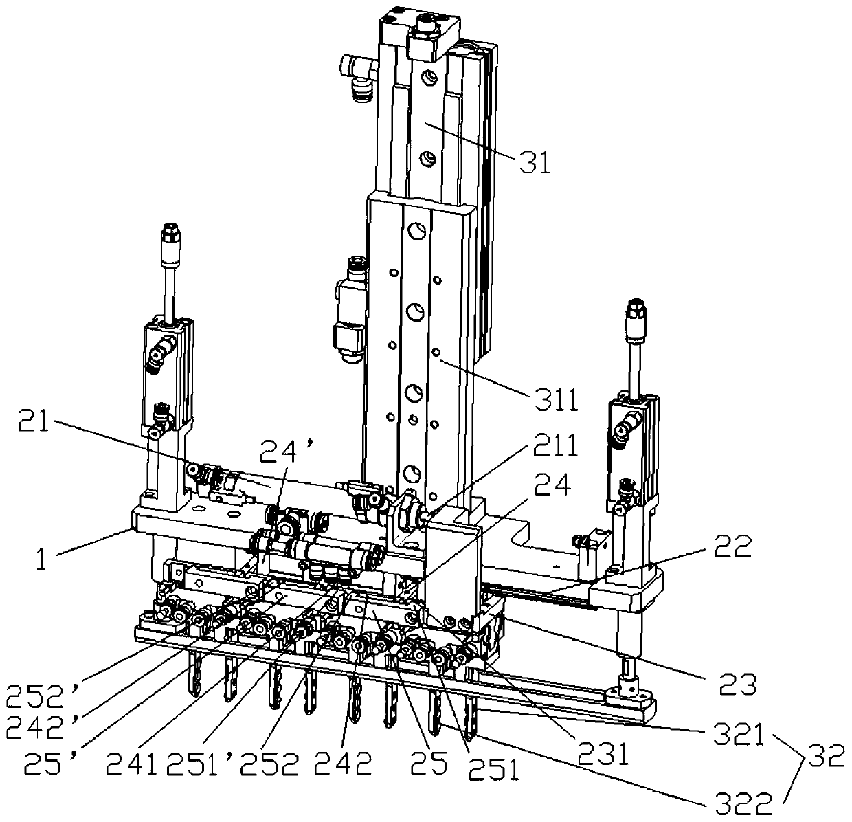
[0047] Such as figure 2 , the cylinder piston rod 311 stretches out to the limit position, the small frame 1 descends, and the holder 32 moves down to the low position along with the device;

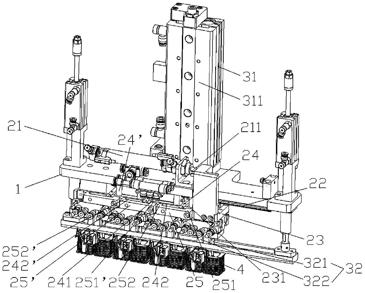
[0048] Such as image 3 , the winding 4 whose spacing is to be adjusted is placed in the low position in advance, and the c...


PUM


Abstract

The invention provides a workpiece spacing adjusting device. The workpiece spacing adjusting device comprises a machine frame, a lateral movement mechanism and a longitudinal movement mechanism, wherein the lateral movement mechanism comprises a first fixed part and a first movable part constrained by the first fixed part, and the first fixed part is fixedly arranged on the small machine frame; the longitudinal movement mechanism comprises a second fixed part and a second movable part constrained by the second fixed part, the second fixed part is fixedly disposed on the machine frame where thedevice is located; the first fixed part comprises a first linear actuator and a guide rail, the first movable part comprises a driving sliding block, a driven sliding block and a connecting rod; thefirst linear actuator is fixedly connected with the driving sliding block; the driving sliding block and the driven sliding block are slidably arranged on the guide rail, one end of the connecting rodis fixedly connected with the driving sliding block, and the other end of the connecting rod is movably connected with the driven sliding block, so that the other end of the connecting rod moves within a limited space; and the first linear actuator drives the driving sliding block to move linearly, when the connecting rod is in a limited position of the limited space, the driving sliding block drives the driven sliding block to move linearly through the connecting rod, the second fixed part is a second linear actuator, the second movable part is a tail end actuator capable of picking and placing workpieces, and the second linear actuator drives the tail end actuator to move longitudinally. According to the workpiece spacing adjusting device, the front end sliding block of a power chain drives the rear end sliding block of the power chain to move conditionally through the connecting rod, a "dead zone" where the connecting rod cannot transmit power is actively manufactured, and the beneficial effect of adjusting the spacing between the workpieces is accurately and flexibly realized.

Description

technical field [0001] The invention relates to the field of industrial automatic production lines, and the IPC classification belongs to B25J3 / 00. Background technique [0002] In an automated production line, when workpieces are transferred between different stations, the distance between workpieces often changes. In order to change the spacing, servo motors are commonly used to drive multiple ball screws, or multiple cylinders are used to individually change the spacing between each workpiece. The mechanical structure is complicated, and the manufacturing and maintenance costs are high. [0003] For terminology and common knowledge, please refer to the "Mechanical Engineering Handbook" and "Electrical Engineering Handbook" published by Mechanical Industry Press in 1983 or 1997, and the national standard GBT 26815-2011 "Industrial Automation Instrument Terminology Actuator Terminology", GB / T 17446 -2012 "Vocabulary of Fluid Transmission Systems and Components" and GB / T 12...

Claims


Application Information

Patent Timeline
Patent Type & Authority Applications(China)
IPC IPC(8): B25J15/10B23Q7/16B23Q41/02
CPCB25J15/10B23Q7/16B23Q41/02
Inventor 潘才璋薛雨龙赵小凡
Owner HANYU GRP CO LTD
Why Eureka
Try Eureka