Precise Positioning Ultrasonic Motor Excited by Dual Vibrator Combined Ultrasonic Vibrator

An ultrasonic vibrator, ultrasonic motor technology, applied in piezoelectric effect/electrostrictive or magnetostrictive motors, generators/motors, electrical components, etc., can solve the problems of small output force, reduce resonance operating frequency, etc. The effect of reducing running error, eliminating return error and flexible application

Inactive Publication Date: 2016-03-02
HARBIN INST OF TECH
View PDF17 Cites 0 Cited by
  • Summary
  • Abstract
  • Description
  • Claims
  • Application Information

AI Technical Summary

Problems solved by technology

In order to reduce the resonant operating frequency of the motor stator, a threaded linear motor driven by a piezoelectric composite bending beam whose stator is fixed at one end with a cantilever beam structure is proposed. For example, the patent number is CN200910080339.6. This type of motor mainly uses a columnar cantilever The coupling of the space-orthogonal bending vibration mode of the beam structure stator generates driving traveling waves to realize the motion output of the output shaft; another representative thread-driven cylindrical rotary-linear ultrasonic motor mainly has a stator with a piezoelectric sheet pasted on it. There are two types of ultrasonic lead screw motors, metal tube type and piezoelectric tube type, such as patent No. Two first-order bending vibrations that are orthogonal to each other in the space of the end-free restrained cylindrical stator generate driving traveling waves on the inner surface of the free end of the stator. Rotation-linear motion output of the output shaft; the piezoelectric elements used in the aforementioned thread-driven ultrasonic motor stators mostly use d 31 Vibration mode has certain advantages in the miniaturization of motors, especially for ultrasonic lead screw motors, this advantage is more obvious, but there is inevitably the practical problem of small output force

Method used


Image

  • Precise Positioning Ultrasonic Motor Excited by Dual Vibrator Combined Ultrasonic Vibrator
  • Precise Positioning Ultrasonic Motor Excited by Dual Vibrator Combined Ultrasonic Vibrator
  • Precise Positioning Ultrasonic Motor Excited by Dual Vibrator Combined Ultrasonic Vibrator

Examples


specific Embodiment approach 1

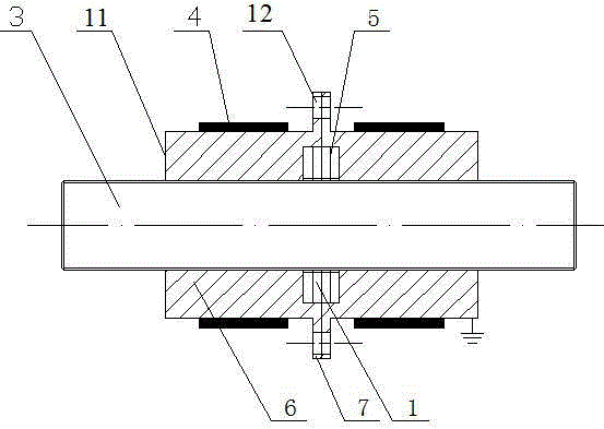
[0032] Specific implementation mode one: see Figure 1 to Figure 5 , the precise positioning ultrasonic motor excited by the dual vibrator combined ultrasonic vibrator, the precise positioning ultrasonic motor excited by the dual vibrator combined ultrasonic vibrator mainly includes a threaded output shaft 3, a linear actuator 5, a plurality of exciting elements 4 and two An ultrasonic vibrator 11, the ultrasonic vibrator 11 is a columnar elastic body, the ultrasonic vibrator 11 includes a vibrated main body 6 and a combined locking end 7, the combined locking end 7 is located at one end of the vibrated main body 6 and the two are integrated, combined The locking end 7 is a protruding disc-shaped structure, and the center of the other end of the excited body 6 is provided with a threaded hole 9, combined with the center of the locking end 7, a cylindrical concave cavity 8 is provided for the built-in installation of the linear actuator 5, threaded The hole 9 is coaxial with th...

specific Embodiment approach 2

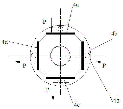
[0035] Specific embodiment 2: The precise positioning ultrasonic motor excited by the double vibrator combined ultrasonic vibrator described in the specific embodiment 1, the outer peripheral side of the excited main body 6 is uniformly processed with at least four structurally symmetrical square orientations. flat sides (eg figure 2 and image 3 ) or groove ( Figure 4 and Figure 5 ), the number of vibration elements 4 is consistent with the number of flat sides or grooves, and one vibration element 4 is fixed on each flat side or in the groove (the vibration element 4 is fixed by cold welding or epoxy resin glue on the flat side or in the groove, making the structure of the ultrasonic vibrator 11 more compact).

specific Embodiment approach 3

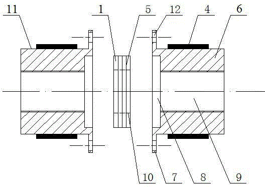
[0036] Specific implementation mode three: as Figure 6~Figure 11 As shown, the precise positioning ultrasonic motor excited by the dual vibrator combined ultrasonic vibrator mainly includes a threaded output shaft 3, a linear actuator 5, and a plurality of exciting elements 4 , two threaded auxiliary driving elements 2 and two ultrasonic vibrators 11, the ultrasonic vibrator 11 is a cylindrical elastic body, the ultrasonic vibrator 11 includes an excited main body 6 and a combined locking end 7, and the combined locking end 7 is located on the excited main body 6 One end and the two are integrated, the combined locking end 7 is a protruding disc-shaped structure, the center of the other end of the excitation main body 6 is provided with a threaded auxiliary driving element mounting hole, and the center of the combined locking end 7 is provided with a cylindrical concave cavity 8, For the built-in installation of the linear actuator 5, the mounting hole of the threaded auxilia...


PUM


Abstract

The invention provides a double-vibrator combined type precise positioning ultrasonic motor excited by ultrasonic vibrators, belongs to the field of ultrasonic vibration application and aims at further improving the output performance of a thread pair drive ultrasonic motor and the linear positioning accuracy of the motor. The ultrasonic motor mainly comprises a thread output shaft, a linear actuator and two ultrasonic vibrators. Fixedly connected shock excitation elements are evenly are arranged in flat lateral sides or grooves of ultrasonic vibrator main bodies, and two combined locking end faces of the ultrasonic vibrators are locked in matching mode. The linear actuator is located in a cylindrical cavity formed by the locking end faces between the two ultrasonic vibrators. The thread output shaft is paired with central thread holes of the ultrasonic vibrators to perform output rotation and linear motion, and a central thread pair can be a replaceable thread pair drive element. The locking between the ultrasonic vibrators and the thread output shaft is achieved by controlling extension of the linear actuator. The double-vibrator combined type precise positioning ultrasonic motor excited by the ultrasonic vibrators can achieve flexible output, and can be used for the fields of aerospace, automobile industry, automation, medical apparatuses and instruments, optical driving, precise positioning systems and the like.

Description

technical field [0001] The invention belongs to the field of ultrasonic vibration application, in particular to a precision positioning ultrasonic motor excited by a combined ultrasonic vibrator. Background technique [0002] Based on the principle of ultrasonic driving, the ultrasonic motor is driven by the screw pair of the bending vibration mode of the cylindrical stator (also called the ultrasonic vibrator), mainly by exciting at least two bending vibration modes in the stator space, and using the coupling of vibration to generate the driving force on the inner surface of the stator. Traveling wave, realizing the rotation-linear motion output of the threaded rod output shaft. This type of threaded pair-driven ultrasonic motor has the characteristics of simple structure, high output force / mass ratio density, easy miniaturization, and high positioning accuracy. [0003] At present, there are several typical structures of ultrasonic motors driven by screw pairs: the stator...

Claims


Application Information

Patent Timeline
Patent Type & Authority Patents(China)
IPC IPC(8): H02N2/00H02N2/04H02N2/12H02N2/08H02N2/16
Inventor 肖才伟程廷海程小军
Owner HARBIN INST OF TECH
Why Eureka
Try Eureka