High-thrust precision-positioning ultrasonic motor excited by multi-vibrator combined ultrasonic vibrator

An ultrasonic vibrator and precise positioning technology, applied in piezoelectric effect/electrostrictive or magnetostrictive motors, generators/motors, electrical components, etc. Strong force/torque output, achieving the effect of precise drive positioning

Inactive Publication Date: 2015-11-25
HARBIN INST OF TECH
View PDF17 Cites 0 Cited by
  • Summary
  • Abstract
  • Description
  • Claims
  • Application Information

AI Technical Summary

Problems solved by technology

This type of motor mainly uses the coupling of the spatially orthogonal bending vibration mode of the stator of the columnar cantilever beam structure to generate driving waves to realize the motion output of the output shaft; another representative thread-driven cylindrical rotary-linear ultrasonic motor mainly There are two types of ultrasonic lead screw motors, the metal tube type and the piezoelectric tube type with stators pasted with piezoelectric sheets. For example, the patent numbers are US2006049720-A1, US2005258714-A1, US7170214-B2, US7309943-B2, CN101040395A and CN1879232A. The ultrasonic guided screw motor mainly utilizes two first-order bending vibrations that are orthogonal to each other in the space of the free-constrained cylindrical stator at both ends to generate driving traveling waves on the inner surface of the free end of the stator, and the stator and the output shaft are driven by a screw pair. The rotation-linear motion output of the output shaft is realized under the action of axial load force; the piezoelectric element used in the stator of the thread-driven ultrasonic motor mentioned above is mostly used d 31 Vibration mode has certain advantages in the miniaturization of motors, especially for ultrasonic lead screw motors, this advantage is more obvious, but there is inevitably the practical problem of small output force

Method used


Image

  • High-thrust precision-positioning ultrasonic motor excited by multi-vibrator combined ultrasonic vibrator
  • High-thrust precision-positioning ultrasonic motor excited by multi-vibrator combined ultrasonic vibrator
  • High-thrust precision-positioning ultrasonic motor excited by multi-vibrator combined ultrasonic vibrator

Examples


specific Embodiment approach 1

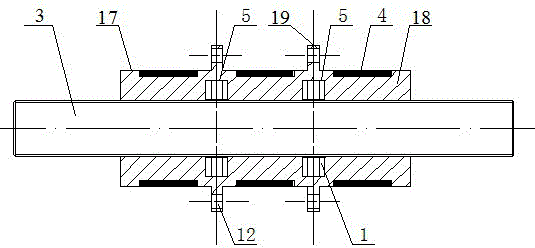
[0029] Specific implementation mode one: as Figure 1 to Figure 4 , a large-thrust precision positioning ultrasonic motor excited by multi-vibrator combined ultrasonic vibrators, said multi-vibrator combined ultrasonic vibrator excited high-thrust precise positioning ultrasonic motor mainly includes a threaded output shaft 3, at least three ultrasonic vibrators 17, at least two A linear actuator 5 and a plurality of excitation elements 4, the ultrasonic vibrator 17 is a cylindrical elastic body, at least three ultrasonic vibrators 17 are coaxial and arranged in a line, and at least three ultrasonic vibrators 17 include at least three excited bodies 18 And at least four combined locking ends 19, one end of the excited main body 18 at the end of the at least three ultrasonic vibrators 17 that are coaxial and arranged in a line is affixed to the middle part of a combined locking end 19, and the rest Both ends of the excited main body 18 (also known as the intermediate ultrasonic ...

specific Embodiment approach 2

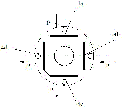
[0031] Specific implementation mode two: as Figure 1 to Figure 4 , Specific Embodiment 1 In the high-thrust precision positioning ultrasonic motor excited by the multi-vibrator combined ultrasonic vibrator, the outer peripheral side of each excited main body 18 is uniformly processed with four flat sides or concave sides with a symmetrical structure and a square orientation. Groove, the number of vibration elements 4 is consistent with the number of flat sides or grooves, and one vibration element 4 is fixed on each flat side or in the groove (the vibration element 4 is fixed on the flat surface by cold welding or epoxy glue) on the side or in the groove, making the structure of the ultrasonic vibrator 17 more compact).

specific Embodiment approach 3

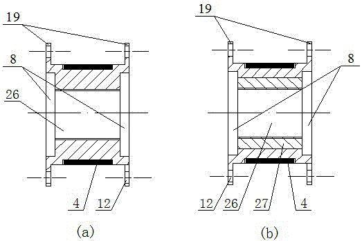
[0032] Specific implementation mode three: as figure 1 with Figure 4 As shown, the multi-vibrator combined ultrasonic vibrator excitation high-thrust precision positioning ultrasonic motor described in the first embodiment, the linear brake 5 is assembled and packaged by piezoelectric stacked sheets 1, and the two ends of the linear brake 5 are compressed They are paired and installed in two corresponding cylindrical concave cavities 8 .


PUM


Abstract

The invention provides a multi-vibrator combined large-thrust precision positioning ultrasonic motor excited by ultrasonic vibrators, belongs to the field of ultrasonic vibration application and aims at further improving the output performance of a thread pair driving ultrasonic motor, generating large thrust and improving positioning accuracy of the motor. The multi-vibrator combined large-thrust precision positioning ultrasonic motor mainly comprises more than two combined ultrasonic vibrators capable of working independently, a linear actuator, a thread pair driving element and a thread output shaft, wherein an excitation element is fixed on the flat lateral surface of an excited main body or fixed in a groove of the excited main body, two end surface of the linear actuator are arranged in two adjacent ultrasonic vibrators in pressing pairing mode, the thread output shaft is respectively connected with two head-end ultrasonic vibrators and at least one internal thread shaft sleeve in threaded mode to be in output rotating and linear movement, and locking of the ultrasonic vibrators and the thread output shaft is achieved by extending or shortening the linear actuator. The multi-vibrator combined large-thrust precision positioning ultrasonic motor can achieve flexible output and is applied to the fields including aeronautics and astronautics, the automobile industry, automation, medical equipment, optical driving and precision positioning.

Description

technical field [0001] The invention belongs to the field of ultrasonic vibration applications, and in particular relates to a multi-vibrator combined ultrasonic vibrator-excited high-thrust precision-positioning ultrasonic motor. Background technique [0002] Based on the principle of ultrasonic driving, the ultrasonic motor is driven by the screw pair of the bending vibration mode of the cylindrical stator (also called the ultrasonic vibrator), mainly by exciting at least two bending vibration modes in the stator space, and using the coupling of vibration to generate the driving force on the inner surface of the stator. Traveling wave, realizing the rotation-linear motion output of the threaded rod output shaft. This type of threaded pair-driven ultrasonic motor has the characteristics of simple structure, high output force / mass ratio density, easy miniaturization, and high positioning accuracy. [0003] At present, there are several typical structures of ultrasonic motor...

Claims


Application Information

Patent Timeline
Patent Type & Authority Patents(China)
IPC IPC(8): H02N2/00H02N2/04H02N2/12H02N2/08H02N2/16
Inventor 程廷海肖才伟程小军
Owner HARBIN INST OF TECH
Why Eureka
Try Eureka