Construction method for reinforcing existing line-spanning bridge by newly-added pier stud bearing steel trussed beams

A construction method and steel truss girder technology, applied in bridge reinforcement, bridge, bridge construction, etc., can solve the deviation between the actual operation state and the theoretical state of the bridge suspender cable force, cracking and damage cracks on the corbel on the beam, and damage to the suspender structure. Uneven force and other problems, to achieve the effect of improving structural stability, improving construction efficiency, and reducing requirements

Active Publication Date: 2020-06-02
ZHEJIANG UNIV CITY COLLEGE
View PDF7 Cites 1 Cited by
  • Summary
  • Abstract
  • Description
  • Claims
  • Application Information

AI Technical Summary

Problems solved by technology

[0003] After investigation and research, it is found that in most of the old dangerous basket arch bridges, there are problems such as uneven stress on the suspender structure and insufficient safety factor of some suspenders, and the cracks and damage of the corbels on the beams are serious and the cracks have obvious development. There are cracks in the joints, which may easily lead to a large deviation between the actual operating state and the theoretical state of the bridge suspender cable force
In the current status of the bridge, the anti-aging fatigue ability of the suspender material and the level of construction technology are difficult to fundamentally solve the problems of water accumulation in the anchor head protective cover of the old dangerous basket arch bridge, anchor head corrosion and suspender cable force loss.

Method used


Image

  • Construction method for reinforcing existing line-spanning bridge by newly-added pier stud bearing steel trussed beams
  • Construction method for reinforcing existing line-spanning bridge by newly-added pier stud bearing steel trussed beams
  • Construction method for reinforcing existing line-spanning bridge by newly-added pier stud bearing steel trussed beams

Examples


Embodiment Construction

[0045] The present invention will be further described below in conjunction with the examples. The description of the following examples is provided only to aid the understanding of the present invention. It should be pointed out that for those skilled in the art, without departing from the principle of the present invention, some improvements and modifications can be made to the present invention, and these improvements and modifications also fall within the protection scope of the claims of the present invention.

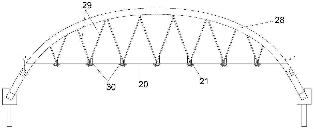
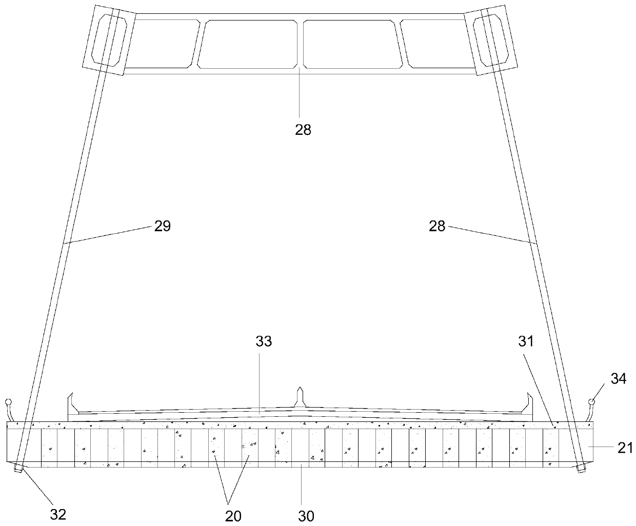
[0046] combined with figure 1 to attach Figure 17 As shown, the construction method of the newly added pier column bearing steel truss girder to reinforce the bridge spanning the existing line includes the following steps:

[0047] Step 1: Construction of the under-bridge support system at the bottom of the bridge;

[0048] Step 2: Remove the bridge deck pavement 33, bridge deck 31 and railing 34 and other appendages at the sidewalks on both sides of the origi...


PUM


Abstract

The invention relates to a construction method for reinforcing an existing line-spanning bridge by newly-added pier stud bearing steel trussed beams. The construction method comprises the steps of 1,constructing an under-bridge supporting system at the bottom of the bridge; 2, dismantling bridge deck pavement, bridge deck slabs and handrails at sidewalks on the two sides of the original bridge; 3, performing mounting operation of the prestress pushing system below the bridge; 4, pushing out and dismounting the concrete longitudinal beams on the two sides of the bridge through a prestress pushing system; 5, pushing the lower chords of the steel longitudinal beams to specified positions through a pushing system, welding the upper chords and the lower chords, and welding the steel longitudinal beams of the adjacent sections; 6, vertically jacking the steel longitudinal beams; and 7, recovering the structure of the bridge floor, and removing the pushing system. The method has the beneficial effects that a steel longitudinal beam pushing system is adopted for construction, the construction operation is mainly carried out under the bridge, the space of the bridge floor does not need tobe occupied, and therefore the influence on traffic is reduced.

Description

technical field [0001] The invention relates to the technical field of bridge reinforcement and transformation construction, in particular to a construction method for reinforcing a bridge spanning an existing line with newly added pier columns bearing steel truss girders. Background technique [0002] With the rapid development of my country's economy, society and transportation, expressways are rapidly extending to areas with complex terrain and geological conditions, bridges account for an increasing proportion of the total length of the route, and bridges are increasingly bearing more frequent and heavy loads than expected in the design. The load of traffic vehicles also puts forward higher requirements on the traffic capacity of existing bridges. After some bridges have been put into operation for several years, there are more or less potential safety hazards due to problems such as heavy traffic and overweight loads. Therefore, the reinforcement of old dangerous bridges...

Claims


Application Information

Patent Timeline
Patent Type & Authority Applications(China)
IPC IPC(8): E01D22/00
CPCE01D22/00
Inventor 王新泉刁红国
Owner ZHEJIANG UNIV CITY COLLEGE
Why Eureka
Try Eureka