Pose estimation method and device based on binocular vision inertial odometer and processor

A binocular vision and odometer technology, applied in the field of robotics, can solve the problems of low positioning accuracy of visual positioning algorithms, and achieve the effects of flexible debugging, reduced cumulative errors, and reduced computing time

Inactive Publication Date: 2020-06-02
GUANGDONG BOZHILIN ROBOT CO LTD
View PDF6 Cites 6 Cited by
  • Summary
  • Abstract
  • Description
  • Claims
  • Application Information

AI Technical Summary

Problems solved by technology

[0006] The main purpose of this application is to provide a method, device, storage medium and processor for estimating pose based on binocular visual inertial odometer, so as to solve the problem of low positioning accuracy of visual positioning algorithm in the prior art

Method used


Image

  • Pose estimation method and device based on binocular vision inertial odometer and processor
  • Pose estimation method and device based on binocular vision inertial odometer and processor
  • Pose estimation method and device based on binocular vision inertial odometer and processor

Examples


Embodiment

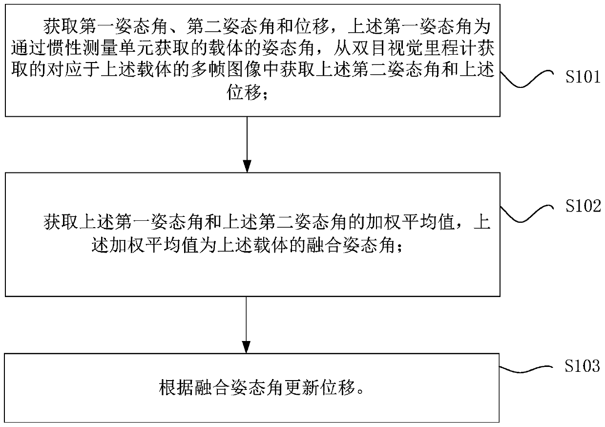
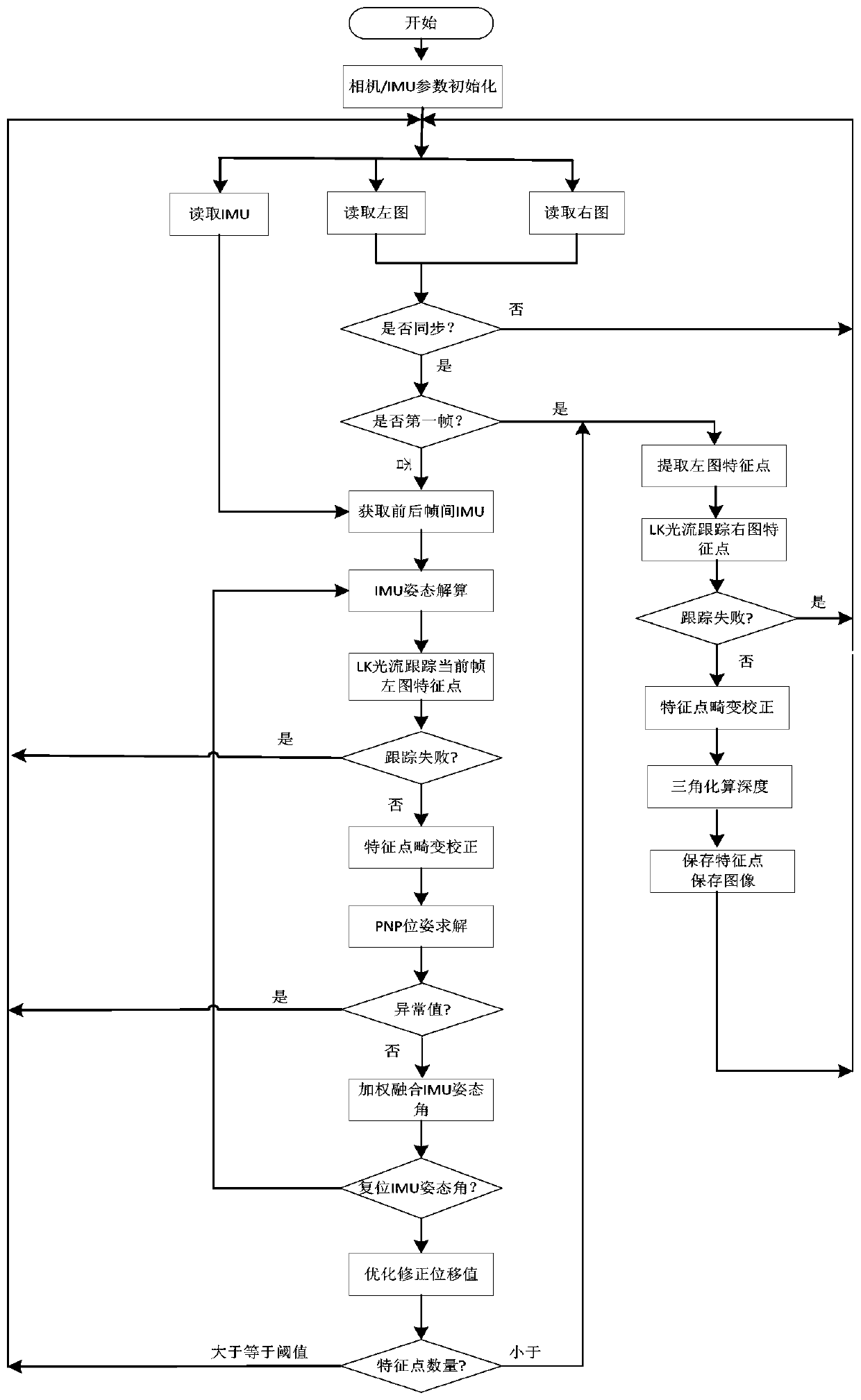
[0095] This embodiment relates to a specific method for estimating pose based on binocular visual-inertial odometer, such as image 3 As shown, it is a flowchart of a method for estimating pose based on binocular visual-inertial odometer, which specifically includes the following steps:

[0096] 1) Initialization of other correlation coefficients such as binocular camera pinhole imaging model parameters, inertial measurement unit device error model parameters, etc.;

[0097] 2) Collect the left and right images of the binocular camera and the original output of the inertial measurement unit;

[0098] 3) The first frame of image is used as feature point initialization, specifically by extracting Shi-Tomas corner points from the left image, and saving the feature points;

[0099] 4) Use the LK optical flow method to track the feature points extracted on the left picture in the previous step on the right picture, and save the tracking point pair;

[0100] 5) Perform distortion ...


PUM


Abstract

The invention provides a pose estimation method and device based on a binocular vision inertial odometer, a storage medium and a processor. The method comprises steps: obtaining a first attitude angle, a second attitude angle and displacement, wherein the first attitude angle is an attitude angle of a carrier acquired through an inertia measurement unit, and the second attitude angle and displacement are acquired from multiple frames of images corresponding to the carrier acquired by the binocular vision odometer; obtaining a weighted average value of the first attitude angle and the second attitude angle, wherein the weighted average value is a fusion attitude angle of the carrier; and updating the displacement according to the fusion attitude angle. The attitude angles acquired by the inertial measurement unit and the binocular vision odometer are fused, so that the robustness of the fusion system is improved, the operation time of the fusion algorithm is shortened, the fusion algorithm is more flexible to debug, the precision of the attitude angles of the visual odometer is obviously improved, and the positioning precision of a pure visual positioning algorithm is improved through fusion of the two.

Description

technical field [0001] The present application relates to the field of robotics, in particular, to a method, device, storage medium and processor for estimating pose based on binocular visual-inertial odometer. Background technique [0002] At present, with the vigorous development of miniaturized, low-power, and economical mobile robots and drones, it is urgent to solve the realization of positioning functions under low-power platforms. Visual positioning methods, as a way of autonomous positioning, can Effectively solve the error caused by the slipping of wheeled odometers in harsh environments (such as construction sites). At the same time, in the development of construction robots, there are some wheels or motion models that are difficult to model. At this time, only visual odometry can be used to achieve rough positioning. Features. [0003] The traditional visual positioning algorithm based on nonlinear optimization requires too much computing resources and pose outpu...

Claims


Application Information

Patent Timeline
Patent Type & Authority Applications(China)
IPC IPC(8): G01C21/16G01C21/00G01C1/00G01C11/04
CPCG01C1/00G01C11/04G01C21/005G01C21/165
Inventor 袁国斌陶永康贾宁
Owner GUANGDONG BOZHILIN ROBOT CO LTD
Why Eureka
Try Eureka