
Miniaturized Beam Steerable RFID Reader Antenna Based on Pattern Reconfiguration

A directional diagram and reader technology, which is applied in the directions of antennas, resonant antennas, antenna parts, etc., can solve the problems that RFID readers cannot be applied to space-constrained platforms, and can not be miniaturized, so as to increase beam coverage and structure Simple, wide-beam effects

Active Publication Date: 2021-06-08
CHONGQING PINSHENG TECHNOLOGY CO LTD +1
View PDF11 Cites 0 Cited by
  • Summary
  • Abstract
  • Description
  • Claims
  • Application Information

AI Technical Summary

Problems solved by technology

[0003] At present, the reconfigurable antenna pattern in the prior art can be reconfigurable by loading a PIN tube on the feed network, loading a PIN tube on the radiator to achieve reconfigurability, or by giving different feed phases to multiple ports to achieve reconfigurability. Refactoring and other methods, but are currently implemented in the case of electrically large-sized antennas, which have not been miniaturized and cannot be applied to space-constrained platforms such as RFID readers

Method used


Image

  • Miniaturized Beam Steerable RFID Reader Antenna Based on Pattern Reconfiguration
  • Miniaturized Beam Steerable RFID Reader Antenna Based on Pattern Reconfiguration
  • Miniaturized Beam Steerable RFID Reader Antenna Based on Pattern Reconfiguration

Examples


Embodiment Construction

[0031] Embodiments of the present invention are described below through specific examples, and those skilled in the art can easily understand other advantages and effects of the present invention from the content disclosed in this specification. The present invention can also be implemented or applied through other different specific implementation modes, and various modifications or changes can be made to the details in this specification based on different viewpoints and applications without departing from the spirit of the present invention. It should be noted that, in the case of no conflict, the following embodiments and features in the embodiments can be combined with each other.

[0032] It should be noted that the diagrams provided in the following embodiments are only schematically illustrating the basic ideas of the present invention, and only the components related to the present invention are shown in the diagrams rather than the number, shape and shape of the compo...


PUM

PropertyMeasurementUnit
radiusaaaaaaaaaa
thicknessaaaaaaaaaa
heightaaaaaaaaaa

Abstract

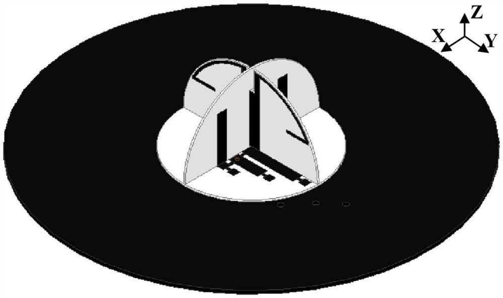
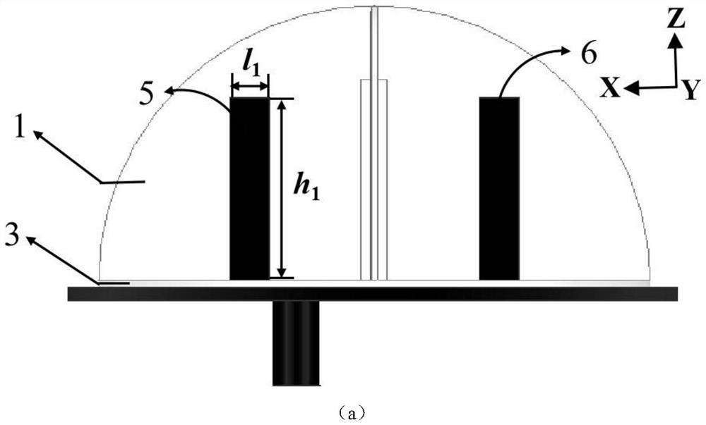
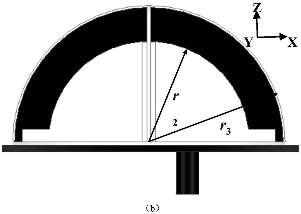
The present invention provides a miniaturized beam steerable RFID reader antenna based on pattern reconfigurability, which includes: a magnetic dipole unit, an electric monopole unit, a dielectric substrate, a feeder ground plate and an antenna for switching the state pattern Reconfigurable feed structure; the dielectric substrate includes a first dielectric substrate arranged along the x-axis, a second dielectric substrate arranged along the y-axis, and a third dielectric substrate arranged along the horizontal plane, the first dielectric substrate and the second dielectric substrate are orthogonal It is arranged on the third dielectric substrate, the magnetic dipole unit is arranged on the first dielectric substrate, the electric monopole subunit is arranged on the second dielectric substrate, and the reconfigurable feeding structure is arranged on the third dielectric substrate; The combination of poles and electric monopoles realizes the miniaturization of the antenna, can realize the reconfiguration of the pattern of two states at the same frequency point, and increases the coverage of the beam; the present invention has high gain, wide beam range, etc. It has good radiation characteristics, and has the characteristics of simple structure and low cost.

Description

technical field [0001] The invention relates to the communication field, in particular to a miniaturized beam controllable RFID reader antenna based on pattern reconfiguration. Background technique [0002] With the rapid development of wireless communication systems, the development of antenna technology is changing with each passing day. Reconfigurable antennas are used in military and civilian applications such as radars and RFID reader antennas to achieve side-fire patterns and monopole pattern patterns in the +Z axis direction. fields have a very wide range of applications. The pattern reconfigurable antenna can switch between the broadside pattern and the monopole pattern pattern with null notching under the condition of constant frequency, and improve the system capacity by multiplexing the same channel and space. And align the main beam of the high-gain broadside pattern with the desired signal to achieve long-distance reception, and then switch to the monopole patt...

Claims


Application Information

Patent Timeline
Patent Type & Authority Patents(China)
IPC IPC(8): H01Q1/22H01Q1/38H01Q1/48H01Q1/50H01Q3/24H01Q9/16H01Q9/30
CPCH01Q1/2216H01Q1/38H01Q1/48H01Q1/50H01Q3/24H01Q9/16H01Q9/30
Inventor 庞静周昌伟唐明春陈英杰付靖峰
Owner CHONGQING PINSHENG TECHNOLOGY CO LTD
Learn More