Permanent magnet synchronous motor speed control method and device, computer equipment and medium

A permanent magnet synchronous motor and speed control technology, applied in the field of computer equipment and medium, device, and permanent magnet synchronous motor speed control method, can solve the problems of high-frequency torque ripple, complicated operation, and operation lag of vector speed control system, etc. Achieve the effect of improving the observation ability, improving the accuracy of the flux linkage, and improving the accuracy and robustness.

Pending Publication Date: 2020-06-02
合肥阳光电动力科技有限公司
View PDF7 Cites 0 Cited by
  • Summary
  • Abstract
  • Description
  • Claims
  • Application Information

AI Technical Summary

Problems solved by technology

However, a high-precision mechanical position sensor will increase hardware costs and later maintenance costs, and will also reduce the reliability of the vector speed control system of the entire permanent magnet synchronous motor
[0004] Based on the traditional method, the speed of the permanent magnet synchronous motor is controlled based on the speed sensor, that is, the rotor position and speed are estimated by using a suitable estimation method without increasing the hardware cost. The current methods are: one is based on the motor The open-loop calculation method of the ideal model adopts the open-loop algorithm based on the mathematical model of the motor, such as the direct calculation method, the estimation method based on the inductance change, and the back electromotive force integration method. Although the calculation process is simple, it has a strong influence on the motor parameters. Dependence, when the parameters change or the system is in a dynamic change, it will affect the accuracy of the speed estimation results of the permanent magnet synchronous motor
The second is a closed-loop algorithm based on various observer models, such as extended Kalman filter, sliding mode observer, model reference adaptive algorithm, phase-locked loop algorithm based on back EMF and other adaptive algorithms, but various algorithms All have different limitations, coupled with other interference factors, cannot accurately estimate rotor speed and position
The third is the high-frequency injection identification algorithm. In the low-speed or even zero-speed condition of the motor, the high-frequency excitation signal is injected to obtain the rotor position information. If the filter is selected properly, a better identification effect can be obtained, but its calculation is complex and Filtering can easily cause the vector speed regulation system of the permanent magnet synchronous motor to lag behind, and at the same time cause high-frequency torque ripple and is not suitable for high-speed operation

Method used


Image

  • Permanent magnet synchronous motor speed control method and device, computer equipment and medium
  • Permanent magnet synchronous motor speed control method and device, computer equipment and medium
  • Permanent magnet synchronous motor speed control method and device, computer equipment and medium

Examples


Embodiment 1

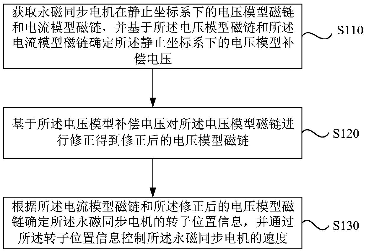
[0045] figure 1 It is a flow chart of a permanent magnet synchronous motor speed control method provided by Embodiment 1 of the present invention. This embodiment is applicable to the situation where the rotor speed and position of the permanent magnet synchronous motor are reasonably estimated without increasing the hardware cost. The method can be executed by the speed control device of the permanent magnet synchronous motor, and the device can be implemented in the form of software and / or hardware. Specifically include the following steps:

[0046]S110. Obtain the voltage model flux linkage and current model flux linkage of the permanent magnet synchronous motor in the stationary coordinate system, and determine the voltage model compensation voltage in the stationary coordinate system based on the voltage model flux linkage and the current model flux linkage .

[0047] Wherein, the voltage model flux linkage is obtained by determining the voltage model back electromotive...

Embodiment 2

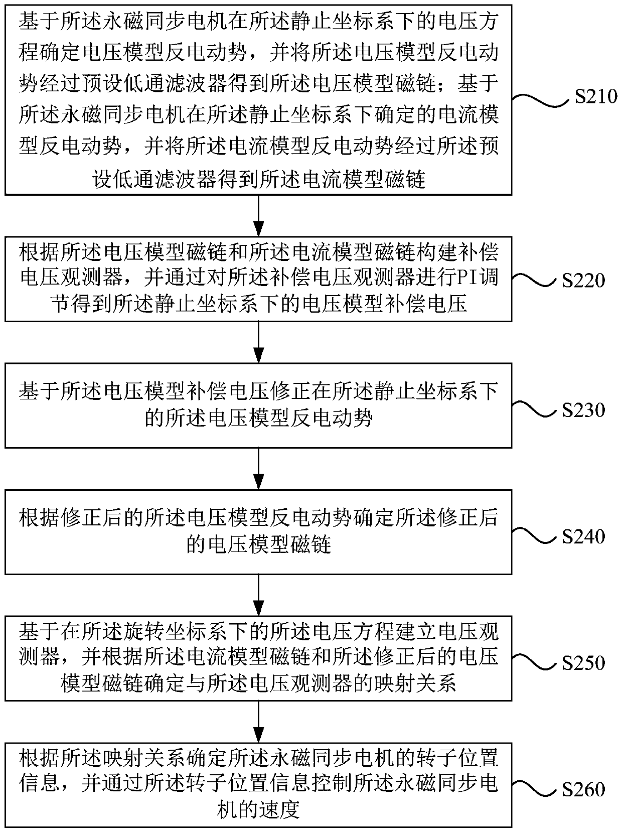
[0062] figure 2 It is a flow chart of a speed control method for a permanent magnet synchronous motor provided by Embodiment 2 of the present invention. This embodiment is optimized on the basis of the foregoing embodiments.

[0063] Correspondingly, the method in this embodiment specifically includes:

[0064] S210. Determine the voltage model back electromotive force based on the voltage equation of the permanent magnet synchronous motor in the stationary coordinate system, and pass the voltage model back electromotive force through a preset low-pass filter to obtain the voltage model flux linkage; and,

[0065] Based on the current model back electromotive force determined in the stationary coordinate system of the permanent magnet synchronous motor, and passing the current model back electromotive force through the preset low-pass filter to obtain the current model flux linkage.

[0066] On the basis of the above embodiments, the voltage model counter electromotive forc...

Embodiment 3

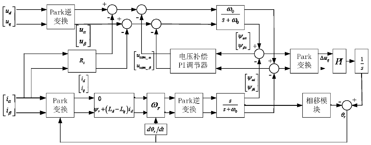
[0117] image 3 It is a control flowchart of a method for controlling the speed of a permanent magnet synchronous motor provided by Embodiment 3 of the present invention. The technical solutions of the embodiments of the present invention are further optimized on the basis of the above embodiments. The method of this embodiment specifically includes:

[0118] Based on the rotating coordinate system of permanent magnet synchronous motor, the extended flux linkage equation is established as [0ψ r +(L d -L q )i d ], the permanent magnet flux linkage, direct axis inductance, quadrature axis inductance and quadrature axis current of the permanent magnet synchronous motor determine the voltage equation under the rotating coordinate system to determine the given of the extended flux linkage, and the extended flux linkage is equivalent to the current based The extension magnet link for the model.

[0119] The extended back electromotive force is obtained according to the extende...


PUM


Abstract

The embodiment of the invention discloses a permanent magnet synchronous motor speed control method and device, computer equipment and a medium. The method comprises the steps of obtaining a voltage model flux linkage and a current model flux linkage of a permanent magnet synchronous motor in a static coordinate system, and determining a voltage model compensation voltage in the static coordinatesystem based on the voltage model flux linkage and the current model flux linkage; correcting the voltage model flux linkage based on the voltage model compensation voltage to obtain a corrected voltage model flux linkage; and determining rotor position information of the permanent magnet synchronous motor according to the current model flux linkage and the corrected voltage model flux linkage, and controlling the speed of the permanent magnet synchronous motor through the rotor position information. According to the technical scheme of the embodiment of the invention, the back electromotive force observation capability and flux linkage precision are improved, and the precision and robustness of speed estimation of the permanent magnet synchronous motor are improved.

Description

technical field [0001] The embodiments of the present invention relate to the technical field of electrical control, and in particular to a speed control method, device, computer equipment and medium of a permanent magnet synchronous motor. Background technique [0002] Due to its compact structure and reliable performance, permanent magnet synchronous motors have been widely used in wind power generation, electric vehicles, ship drives and other fields. [0003] The vector speed regulation of the permanent magnet synchronous motor usually needs to detect or estimate the rotor position to control the voltage, current and speed. The traditional method is to install mechanical sensors to obtain rotor position and speed information as feedback to form closed-loop control. However, a high-precision mechanical position sensor will increase hardware costs and later maintenance costs, and will also reduce the reliability of the vector speed control system of the entire permanent m...

Claims


Application Information

Patent Timeline
IPC IPC(8): H02P21/18H02P21/14H02P25/02
CPCH02P21/18H02P21/141H02P25/022H02P2207/05
Inventor 张英范王辉于安博霍炯冯孝伟
Owner 合肥阳光电动力科技有限公司
Why Eureka
Try Eureka