Copper bar punching and shearing machine

A punching machine, punching technology

Inactive Publication Date: 2020-06-05
上海常青钣金机箱制造有限公司
View PDF11 Cites 4 Cited by
  • Summary
  • Abstract
  • Description
  • Claims
  • Application Information

AI Technical Summary

Problems solved by technology

[0004] Through the cooperation of buffer piles, buffer seats, first springs, connecting rods, second springs, rotating shafts, runners, movable grooves, and soft cushions, the effect of shock absorption can be achieved when the auto parts punching machine is working, which solves the current problem. When some auto parts punching machines are in use, due to the excessive vibration force, the punching effect may be affected
However, this kind of punching machine can only punch holes of one specification at a time. If you want to punch holes of different sizes, you need to replace different punches. The replacement process is cumbersome and affects work efficiency.

Method used


Image

  • Copper bar punching and shearing machine
  • Copper bar punching and shearing machine

Examples


Embodiment Construction

[0032] The present invention will be described in further detail below in conjunction with the accompanying drawings.

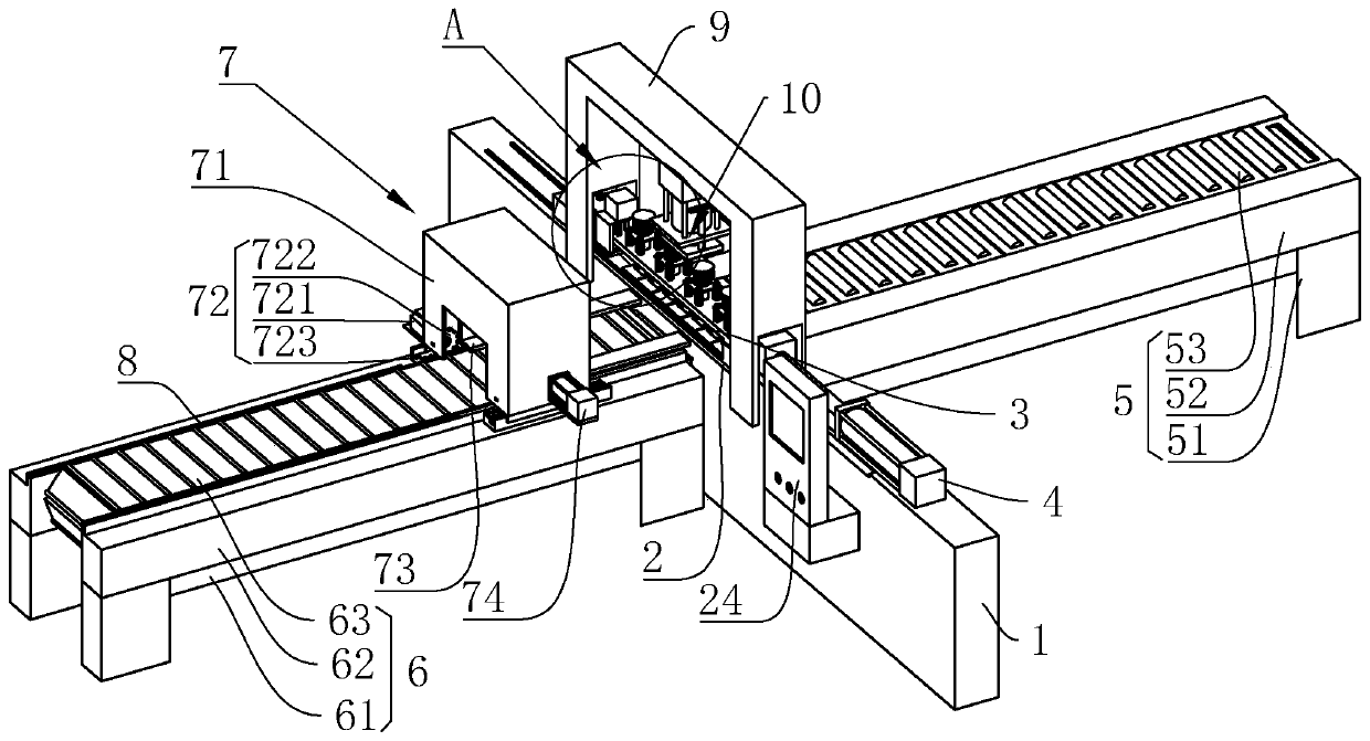
[0033] refer to figure 1 , is a copper bar punching and shearing machine disclosed in the present invention, comprising a cuboid base 1, the base 1 is slid along its length direction and installed with an overall cuboid support plate 2, and the end of the support plate 2 away from the base 1 is fixed by bolts A mold box 3 in the shape of a cuboid is installed, and the base 1 is fixed with bolts to drive the horizontal drive 4 of the mold box 3 to move horizontally. Preferably, the horizontal drive 4 is a hydraulic cylinder. Both sides of the base 1 along its length direction are respectively provided with a feeding mechanism 5 for feeding and a discharging mechanism 6 for discharging. One side of the base 1 is equipped with a console 24 that is in the shape of a cuboid as a whole by bolts.

[0034] The feeding mechanism 5 comprises a feeding support 51, a f...


PUM


Abstract

The invention discloses a copper bar punching and shearing machine. The copper bar punching and shearing machine comprises a base and is characterized in that a supporting plate is slidably arranged on the base, and a mold box is fixedly mounted at the end, away from the base, of the supporting plate; multiple mold heads for punching and a tools for cutting a copper bar are slidably mounted on themold box in the vertical direction, and a buffering groove for punching is formed in the end, away from the base, of the supporting plate; a console for controlling the copper bar punching and shearing machine to work is fixedly arranged on the side wall of the base, a horizontal driving part for driving the mold box to horizontally move is mounted on the base, and a gantry is mounted at the end,close to the supporting plate, of the base; and a vertical driving part for driving the mold heads to slide is mounted on the gantry, a feeding mechanism and a discharging mechanism are arranged on the two opposite side walls of the base correspondingly, and a clamping assembly for clamping a steel copper to move is arranged on the discharging mechanism. The multiple mold heads are mounted on a mold library, multiple holes of different types can be punched, different mold heads do not need to be manually replaced, the punching time is saved, and the work efficiency is improved.

Description

technical field [0001] The invention relates to the technical field of copper bar processing, in particular to a copper bar punching and shearing machine. Background technique [0002] Copper bars are suitable for electrical engineering such as high and low voltage electrical appliances, switch contacts, power distribution equipment, bus ducts, etc., and are also widely used in ultra-high current electrolytic smelting projects such as metal smelting, electrochemical plating, and chemical caustic soda. Punching: refers to the operation of punching various graphics on steel plates, leather, cloth, wood and other materials to meet different needs. Specifically, there are eight-character holes, hexagonal holes, punching plates, long holes, square holes, round holes, punching plate nets, triangular holes, etc. Punching is often done by a special punching machine. [0003] A Chinese invention patent application document with the application number CN201711002371.3 discloses a pu...

Claims


Application Information

Patent Timeline
Patent Type & Authority Applications(China)
IPC IPC(8): B23P23/04
CPCB23P23/04
Inventor 韩承洁
Owner 上海常青钣金机箱制造有限公司
Why Eureka
Try Eureka