
Circular tubular catheter tip forming machine

A catheter tip and molding machine technology, applied in the field of medical devices, can solve problems such as affecting catheter molding, poor environmental adaptability, and temperature rise of induction coils, and achieve the effects of precise control of molding temperature, good molding, and accurate cutting action.

Pending Publication Date: 2020-06-05
中为医疗科技(江苏)有限公司
View PDF0 Cites 1 Cited by
  • Summary
  • Abstract
  • Description
  • Claims
  • Application Information

AI Technical Summary

Problems solved by technology

This structure has the following disadvantages: first, the core needle cannot be accurately controlled to cut off the catheter in the tip forming mold
If the adjustment is not good, the core needle will be cut continuously. The catheter and the core needle will break the mold
Third, air cylinder transmission requires air. In some environments where the air cleanliness is high, the compressed air needed for pneumatics needs to be purified, and the filters on the pneumatic equipment will also pollute the environment.
Fourth, this kind of equipment generally uses water circulation cooling, and the copper induction coil on the heater will scale. Due to the use of circulation cooling and the influence of scaling, the temperature of the cooling water rises, and the scaling in the induction coil also causes the temperature of the induction coil to rise, and the temperature of the cooling water And the temperature rise caused by the fouling of the induction coil will affect the effect of the tube forming, which will only be found when the forming effect is poor; fifth, because the distance and position between the heating induction coil and the forming mold are easy to change, the temperature of the heating tube will not Stable, inconsistent results in catheter molding
Therefore, this kind of equipment has poor environmental adaptability, poor control accuracy, inconvenient use and unhygienic use.

Method used


Image

  • Circular tubular catheter tip forming machine
  • Circular tubular catheter tip forming machine
  • Circular tubular catheter tip forming machine

Examples


Embodiment 1

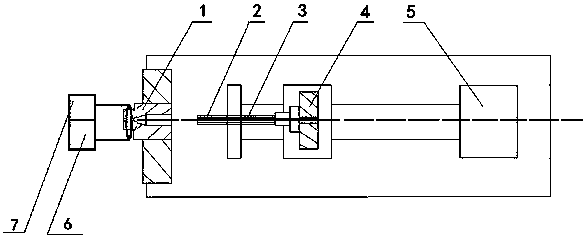
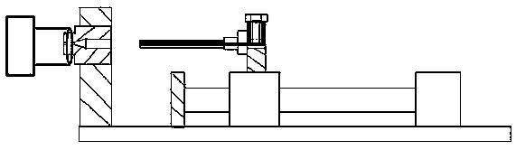
[0019] see figure 1 and figure 2 , Embodiment 1 of the present invention includes:

[0020] A round tubular catheter tip forming machine, comprising a tip forming mold 1, a catheter 2, a core needle 3, a core needle clamp 4, a heating controller 6 and a motor-driven stroke control device, the core needle 3 is fixed on the core needle clamp On the device 4, the core needle clamp 4 is fixed on the motor-driven stroke control device, the catheter 2 is sleeved outside the core needle 3, the heating controller 6 is connected with the tip forming mold 1, and the motor-driven stroke control device will The catheter 2 and the core needle 3 are sent into the tip forming mold 1 to complete the molding, and the stroke of the motor-driven stroke control device is cut off by the catheter 2, and the core needle 3 and the tip forming mold 1 are controlled on and off.

[0021] Install the core needle 3 on the core needle clamp 4, then install the catheter 2 on the core needle 3, set the mo...

Embodiment 2

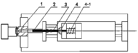
[0026] see image 3 and Figure 4 , Embodiment 2 of the present invention includes:

[0027] A round tubular catheter tip forming machine, comprising a tip forming mold 1, a catheter 2, a core needle 3, a core needle clamp 4, a heating controller 6 and a cylinder-driven stroke control device, the core needle 3 is fixed on the core needle clamp On the device 4, the core needle clamp 4 is fixed on the cylinder-driven stroke control device, the catheter 2 is sleeved outside the core needle 3, the heating controller 6 is connected with the tip forming mold 1, and the cylinder-driven stroke control device will The conduit 2 and the core needle 3 are sent into the tip forming mold 1 to complete the molding, and the stroke of the cylinder-driven stroke control device is cut off by the conduit 2, and the core needle 3 and the tip forming mold 1 are controlled on and off.

[0028] The core needle clamp 4 is connected with a clamp buffer 4-1, and the spring pressure on the clamp buffe...


PUM


Abstract

The invention discloses a circular tubular catheter tip forming machine. The circular tubular catheter tip forming machine comprises a tip forming die, a catheter, a core needle, a core needle clamping device, a heating controller and a stroke control device, the core needle is fixed to the core needle clamping device, the core needle clamping device is fixed to the stroke control device, the catheter is arranged outside the core needle in a sleeving mode, the heating controller is connected with the tip forming die, the stroke control device sends the catheter and the core needle into the tipforming die to complete forming, and the stroke of the stroke control device is controlled by connection and disconnection of the core needle and the tip forming die after the catheter is cut off. Bymeans of the mode, the circular tubular catheter tip forming machine is safer, more sanitary, more reliable and more convenient to use; and the forming temperature is accurately controlled, the cutting action is accurate, the catheter is well formed, the environment suitable for use is wide, and the tip forming die cannot be damaged.

Description

technical field [0001] The invention relates to the field of medical instruments, in particular to a circular tubular catheter tip forming machine. Background technique [0002] At present, the known round tubular catheter tip molding equipment generally consists of the following parts. The first part is the transmission and transmission control system, and the second part is the heating and heating control system. The transmission part consists of core needle clamp, cylinder, cylinder controller, stroke regulator, core needle clamping buffer, tip forming mold and controller; the heating part mainly includes heater, heating induction coil, cooling pipe and controller Wait. Install the plastic catheter on the core needle clamp of the transmission part, the cylinder drives the core needle clamp, and sends the core needle clamp to the heater to heat the induction coil, the heating part is heated, and the catheter is on the core needle and then enters the tip Forming mold. Af...

Claims


Application Information

Patent Timeline
IPC IPC(8): B26F1/44B26F1/38B26D7/10B26D7/24B26D5/00
CPCB26D5/005B26D7/10B26D7/24B26F1/3866B26F1/44
Inventor 徐沁高江
Owner 中为医疗科技(江苏)有限公司
Features
  • Generate Ideas
  • Intellectual Property
  • Life Sciences
  • Materials
  • Tech Scout
  • Unparalleled Data Quality
  • Higher Quality Content
  • 60% Fewer Hallucinations
Learn More