
Rotor wing lifting mechanism for coaxial double rotor wings and flying device

A lifting mechanism and a flying device technology, applied in the aviation field, can solve the problems of not meeting the road driving standards of vehicles, not meeting the design requirements of vehicle driving, small longitudinal structure size, etc. The effect of drag, lowering of body height and center of gravity

Pending Publication Date: 2020-06-05
北京海空行科技有限公司
View PDF0 Cites 3 Cited by
  • Summary
  • Abstract
  • Description
  • Claims
  • Application Information

AI Technical Summary

Problems solved by technology

[0003] Conventional coaxial twin-rotor helicopters have no tail rotor, and the longitudinal structure is small in size. The lift system consists of two rotors with upper and lower coaxial reversing rotors. The height of the coaxial dual-rotor helicopter is much higher than that of the single-rotor helicopter with tail rotor. So far, the upper and lower distances of the coaxial dual-rotor have been fixed. will take up a lot of space
In addition, when the coaxial dual-rotor is used as the lift system of the land-air dual-purpose flying vehicle, due to the high body and center of gravity, it does not meet the driving design requirements of the vehicle, and does not meet the road driving standards of the vehicle.

Method used


Image

  • Rotor wing lifting mechanism for coaxial double rotor wings and flying device
  • Rotor wing lifting mechanism for coaxial double rotor wings and flying device
  • Rotor wing lifting mechanism for coaxial double rotor wings and flying device

Examples


Embodiment

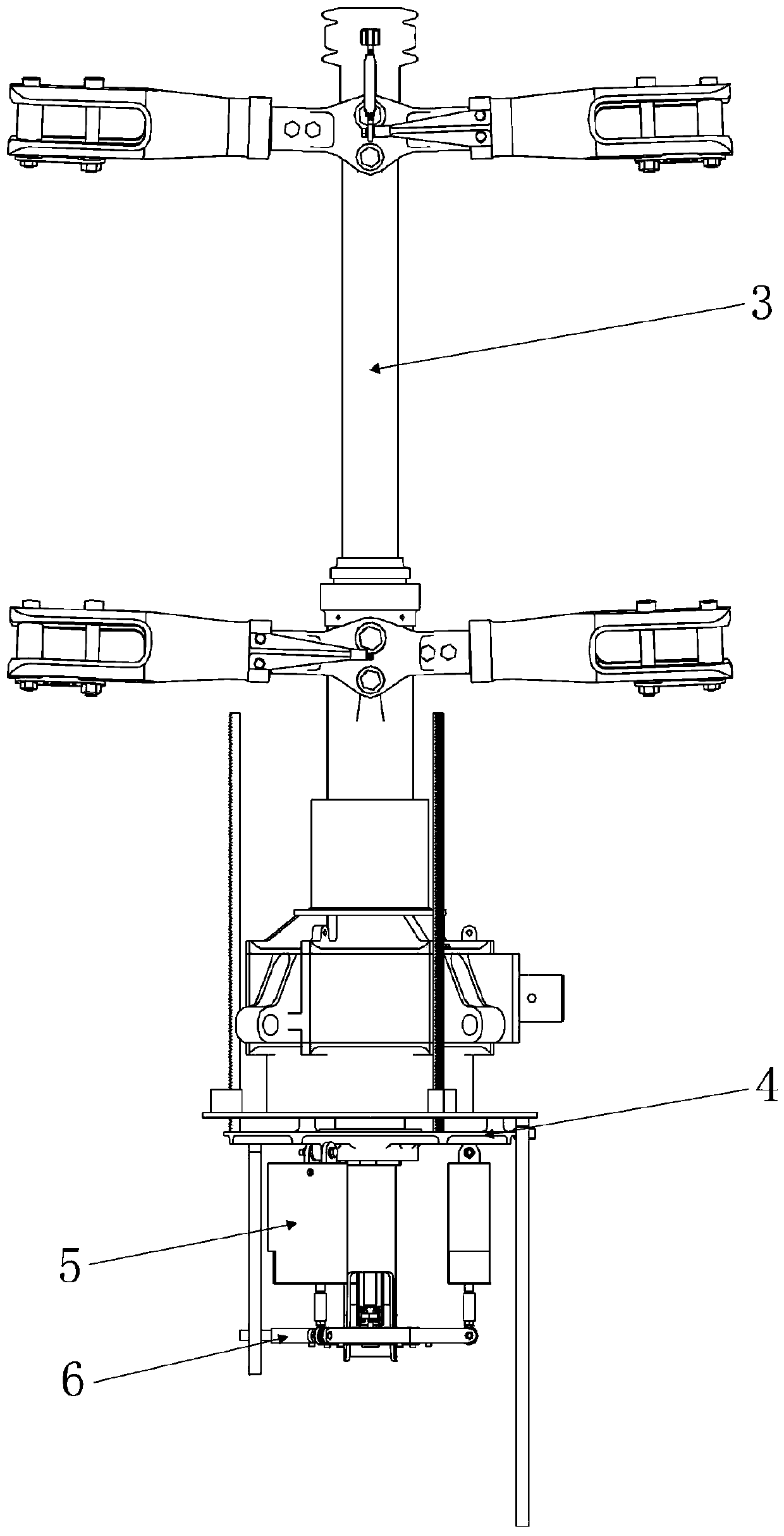
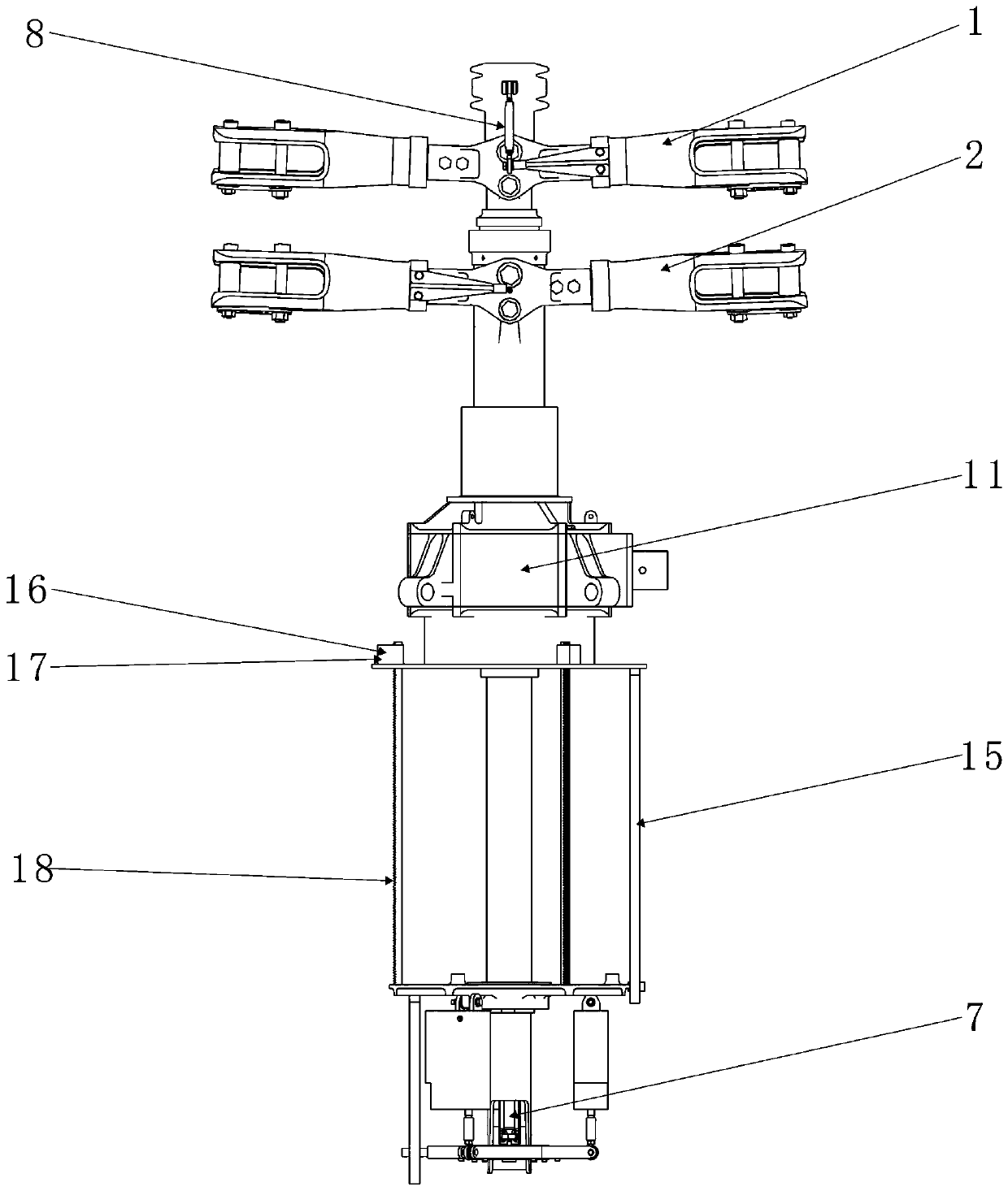
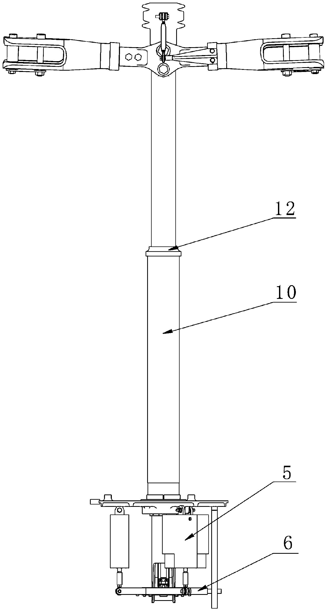
[0050] The following is based on Figure 1-8 A rotor elevating mechanism for coaxial dual rotors and a flying device according to the embodiments of the present invention are described in detail.

[0051] Such as Figure 1-6 As shown, the embodiment of the present invention discloses a rotor elevating mechanism for coaxial double rotors, which includes an upper rotor system 1 and a lower rotor system 2; During conversion, upper rotor system 1 is upward relative to lower rotor system 2;

[0052] specific,

[0053] The above-mentioned rotor elevating mechanism includes: the internal control system of the elevating shaft, the torque transmission system of the elevating shaft, the guiding and positioning system of the elevating shaft and the elevating power system of the elevating shaft.

[0054] The control system in the lifting shaft includes the lifting shaft 3, the reducer base plate 4, and the upper rotor pitch control system; the upper rotor system 1 is installed on the t...


PUM


Abstract

The invention discloses a rotor wing lifting mechanism for coaxial double rotor wings. The rotor wing lifting mechanism comprises a lifting shaft inner control system, a lifting shaft torque transmission system, a lifting shaft guiding and positioning system and a lifting shaft lifting power system which are independent of a transmission system and can slide up and down. The invention further discloses a flight device provided with the rotor wing lifting mechanism. The height size of the coaxial double-rotor helicopter is variable, and the coaxial double-rotor helicopter is more suitable for vehicle-mounted transportation and ground and ship-borne storage; the coaxial type double-rotor flying car is low in gravity center and small in windward resistance during ground running, the stabilityand reliability of the system are improved, the vehicle running design requirement is met, and the vehicle road running standard is met; and the blades with different diameters can be quickly matchedby adjusting the distance between the rotors, so that different load requirements are met, and the aerodynamic efficiency of the coaxial double-rotor helicopter is optimized.

Description

technical field [0001] The invention relates to the field of aviation technology, and more specifically, relates to a rotor elevating mechanism for coaxial double rotors and a flying device. Background technique [0002] Currently common normal helicopters mainly include single-rotor helicopters with tail rotors, tandem twin-rotor helicopters, transverse twin-rotor helicopters and coaxial twin-rotor helicopters. Because there is no tail rotor, the coaxial twin-rotor helicopter has a compact structure and small dimensions. Moreover, the fuselage of the coaxial twin-rotor helicopter is relatively short, and its structural weight and load are all concentrated at the center of gravity of the helicopter, thereby reducing the moment of inertia of the helicopter's pitch and yaw. In addition, coaxial helicopters have high hovering efficiency, aerodynamic symmetry, and large pitch and roll control moments, which are beneficial to shipboard. At present, the main application models o...

Claims


Application Information

Patent Timeline
IPC IPC(8): B64C27/10B64D35/06B60F5/02
CPCB60F5/02B64C27/10B64D35/06
Inventor 陈铭李梁王放徐安安
Owner 北京海空行科技有限公司
Learn More