Directional wire-line coring drilling tool and drilling method thereof

A wireline coring and drilling tool technology, which is applied in the field of drilling, can solve the problems of inner tube drilling tool stuck, inner tube drilling tool stalling and sliding, etc., and achieve the effect of increasing drilling times, high drilling efficiency and improving efficiency

Active Publication Date: 2020-06-05
XIAN RES INST OF CHINA COAL TECH& ENG GROUP CORP
View PDF19 Cites 8 Cited by
  • Summary
  • Abstract
  • Description
  • Claims
  • Application Information

AI Technical Summary

Problems solved by technology

[0003] In order to solve the above problems, the present invention provides a directional wireline core drilling tool and its drilling method, which solves the engineering technical problems of continuous directional coring, and the existing wireline core drilling tools are prone to inner tube drilling during the drilling process. The problem of tool sticking and inner tube drilling tool stalling and sliding during uphole drilling

Method used


Image

  • Directional wire-line coring drilling tool and drilling method thereof
  • Directional wire-line coring drilling tool and drilling method thereof
  • Directional wire-line coring drilling tool and drilling method thereof

Examples


Embodiment 1

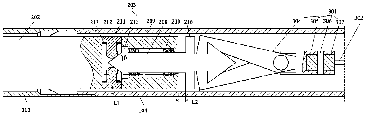
[0043] This embodiment discloses a stall braking device for a directional wireline core drilling tool, such as Figure 4 As shown, the device includes a spear head 208, a brake body 209, a brake spring 210, a block 211, a return spring 212 and a support member 213 for resetting the block 211;

[0044] Wherein, the center of the brake body 209 is provided with a first through hole 214 for setting the spear head 208 through the brake body 209 axially; The first limiting block 215 and the second limiting block 216 are respectively arranged at two ends of the braking body 209 . In this embodiment, the middle part of the spear head 208 is a rod body structure, and both ends are tapered structures, and the first limit block 215 is a disc-shaped flange, which is arranged between the rod body in the middle part of the spear head 208 and one of the tapered ends. ; The second limit block 216 is also a disc-shaped flange, which is arranged near the connection between the other tapered end...

Embodiment 2

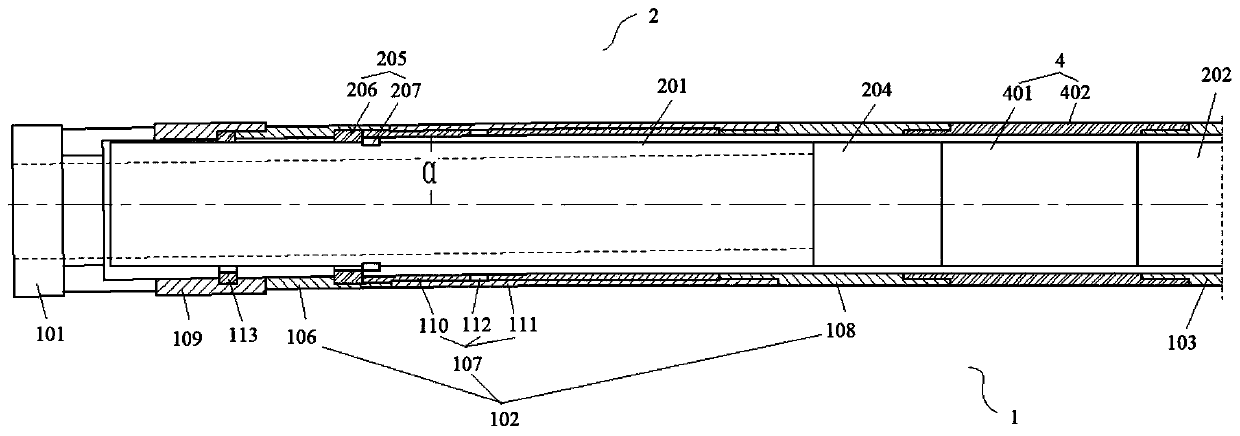
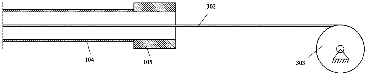
[0049] This embodiment discloses a directional wireline core drilling tool, such as Figure 1 to Figure 3 As shown, the core drilling tool includes an outer pipe unit 1 , an inner pipe unit 2 used in conjunction with the outer pipe unit 1 , and a fishing unit 3 for fishing the inner pipe unit 2 . Wherein, the outer tube unit 1 includes a coring bit 101, an outer tube body 102, a cartridge chamber 103, a coring drill rod 104 and a water stool 105 arranged coaxially in sequence; the inner tube unit 2 includes a rock core arranged coaxially in sequence The pipe 201, the ejection card 202 and the stall braking device 203 that are clamped in the ejection chamber 103, the stall braking device 203 is the stall braking device described in Embodiment 1, wherein the salvage unit 3 and the stall braking device 203 Spearhead 208 connection. The ejection card 202 and the ejection card chamber 103 are conventional structures of drilling tools currently on the market.

[0050] In this embo...

Embodiment 3

[0055] The difference between this embodiment and Embodiment 2 is that the directional wireline coring drilling tool of this embodiment also includes an inclinometer unit 4, and the inclinometer unit 4 includes an inclinometer 401 and a non-magnetic drill pipe pup joint 402, and the non-magnetic drill pipe The puppet 402 is set between the outer tube body 102 and the cartridge chamber 103, the inclinometer 401 is set within the range of the non-magnetic drill pipe puppet 402, and if the impactor 204 is added, it is set between the impactor 204 and the cartridge 103 between. The inclinometer 401 of this embodiment is a storage type inclinometer.

[0056] The inclinometer 401 measures the inclination at equal time intervals, and stores the test data inside the instrument, reads the data or replaces the battery every time the inner tube unit 2 is salvaged, draws the time curve of the hole inclination, and adjusts the coring bit according to the hole inclination data 101 azimuth,...


PUM


Abstract

The invention discloses a directional wire-line coring drilling tool and a drilling method thereof. The drilling tool comprises an outer pipe unit, an inner pipe unit matched with the outer pipe unitfor use and a salvaging unit used for fishing the inner pipe unit; the outer pipe unit comprises a coring drill bit, an outer pipe body, an elastic clamp chamber, a coring drill rod and a water hole which are coaxially arranged in sequence; the inner pipe unit comprises a rock core pipe, an elastic clamp and a stall braking device which are coaxially arranged, wherein the elastic clamp is connected with the elastic clamp chamber in a matched and clamped mode, and the stall braking device is the stall braking device recorded in the invention; and the salvaging unit is connected with a salvagingspearhead of the stall braking device. According to the drilling tool, the azimuth angle of the coring drill bit can be adjusted according to hole deviation data, a drilling track is adjusted, and awhole drill stem column does not need to be lifted out, so that continuous directional coring drilling is achieved, labor force can be greatly saved, drilling return times in unit time are increased,and efficiency is improved.

Description

technical field [0001] The invention relates to the technical field of drilling, in particular to a directional wireline core drilling tool and a drilling method thereof. Background technique [0002] Domestic directional drilling technology is widely used in the field of coal mine and oil exploration. The combined drilling process of wireline coring and screw directional comprehensive drilling is used in oil exploration wells. The continuous directional core drilling technology can grasp and adjust the drilling trajectory of the exploration core hole in a timely manner, so that it can extend along the preset exploration trajectory, increase the radiation area of ​​a single hole, and make the exploration target more clear and specific. At present, there is no related technology in China that can solve the problem of continuous directional coring. Moreover, during the drilling process, the inner tube drilling tool is likely to be stuck, resulting in failure to salvage, and ...

Claims


Application Information

Patent Timeline
Patent Type & Authority Applications(China)
IPC IPC(8): E21B25/16E21B47/022
CPCE21B25/16E21B47/022
Inventor 邹祖杰田宏亮常江华凡东鲁飞飞张阳王振亚
Owner XIAN RES INST OF CHINA COAL TECH& ENG GROUP CORP
Why Eureka
Try Eureka