Supercharge Your Innovation With Domain-Expert AI Agents!

Wind power generator set

A technology for wind turbines and nacelles, which is applied in wind turbines, wind power generation, engines, etc., can solve the problems of many space layout restrictions, and the overall heat dissipation effect of heat exchangers is small, so as to improve heat dissipation capacity, improve structural compactness and Arrangement feasibility, effect of meeting cooling requirements

Active Publication Date: 2020-06-05
ZHEJIANG UNIV +1
View PDF6 Cites 1 Cited by
  • Summary
  • Abstract
  • Description
  • Claims
  • Application Information

AI Technical Summary

Problems solved by technology

[0006] The technical problem to be solved by the present invention is to overcome the defects in the prior art that the space arrangement of multiple heat exchangers of the wind power generating set is limited, which easily leads to a small improvement in the overall heat dissipation effect of the heat exchangers, and to provide a wind power generator unit

Method used


Image

  • Wind power generator set
  • Wind power generator set
  • Wind power generator set

Examples


Embodiment 1

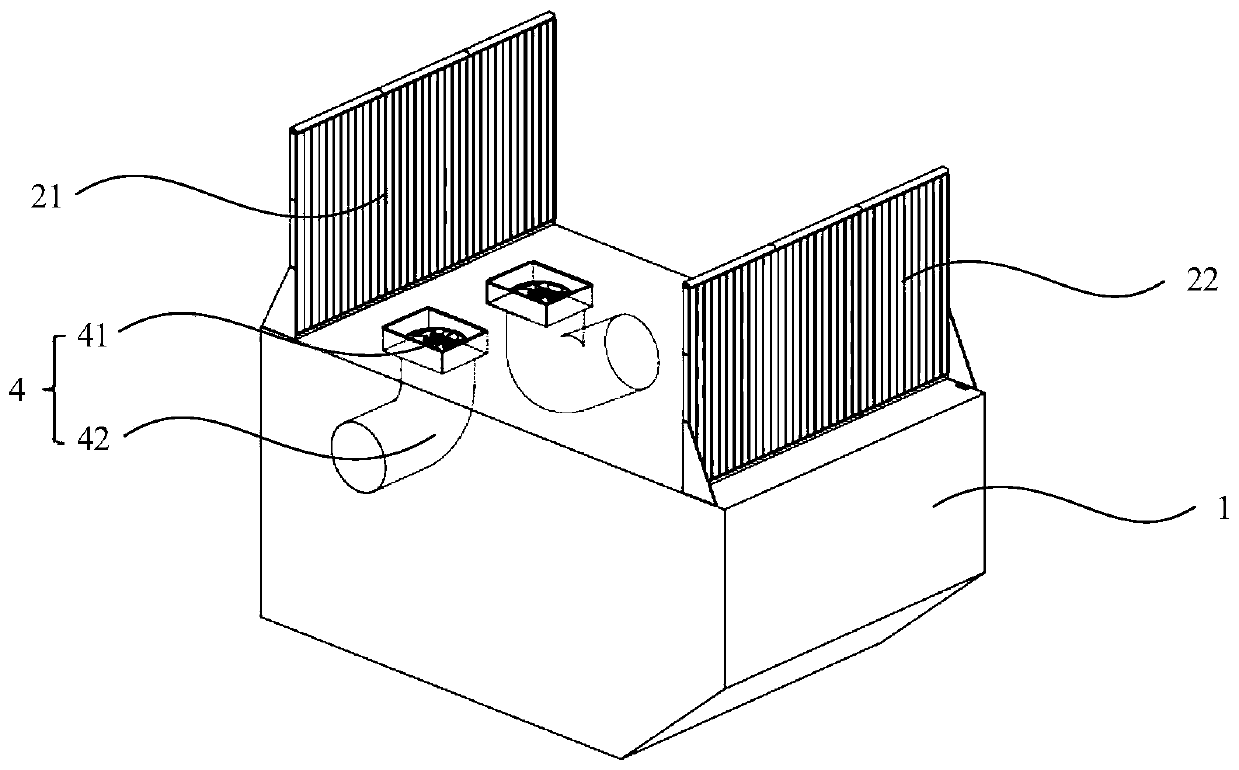
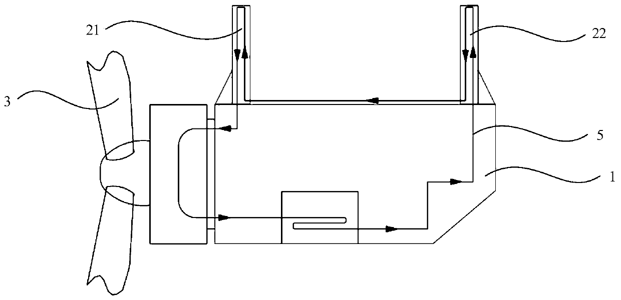
[0046] This embodiment provides a wind power generating set, such as figure 1 As shown, the wind power generating set includes a nacelle 1 and two heat exchangers arranged outside the nacelle 1 and connected to the nacelle 1 . Two heat exchangers are arranged on the first outer surface of the nacelle 1 and arranged at intervals along the axial direction of the wind power generating set. Along the flow direction of the outside air, the heat exchanger located upstream is the upstream heat exchanger 21, and the heat exchanger located downstream is The heat exchanger is the downstream heat exchanger 22 . Wherein, the flow direction of the outside air is from the blades 3 of the wind power generator to the nacelle 1 along the axial direction of the wind power generator.

[0047] It should be noted that the first outer surface of the nacelle 1 refers to the upper end surface of the nacelle 1 in this embodiment, and in other alternative embodiments, the first outer surface can also ...

Embodiment 2

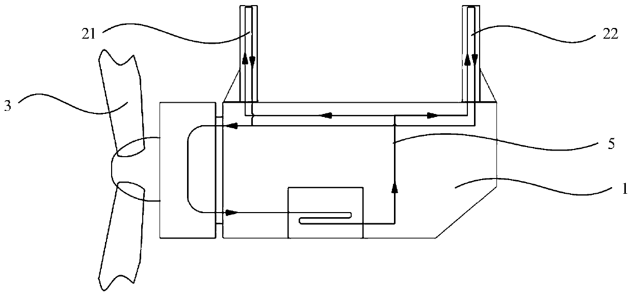
[0069] The structure of this embodiment is basically the same as that of Embodiment 1, the difference is that the location of the suction device 4 is different.

[0070] like Figure 4 As shown, the suction device 4 is arranged between the upstream heat exchanger 21 and the downstream heat exchanger 22, and is arranged close to the leeward end of the upstream heat exchanger 21, so that it can absorb more hot air discharged by the upstream heat exchanger 21 in time. . Air suction device 4 is arranged on the side of heat exchanger, and hot air flows out by the side of heat exchanger, and air suction device 4 is arranged on the side of nacelle 1 so that air suction device 4 can not block the air flow on wind path. In order to ensure the timeliness and uniformity of the suction device 4 absorbing the hot air, heat exchangers should be arranged on both sides of the heat exchanger, so that the hot air can flow out from both sides of the heat exchanger.

[0071] Suction device 4 co...


PUM


Abstract

The invention discloses a wind power generator set. An upstream heat exchanger, a downstream heat exchanger and an air suction device are included. The air suction device is arranged between the upstream heat exchanger and the downstream heat exchanger and used for absorbing hot air exhausted by the upstream heat exchanger so that a low-air-pressure area can be formed at the leeward end of the upstream heat exchanger. Outside air can flow towards the low-air-pressure area and flows to the downstream heat exchanger and / or outside air can flow towards the low-air-pressure area from the downstream heat exchanger. Most of hot air flowing out of the upstream heat exchanger is absorbed and exhausted by the air suction device, most of outside air flowing into the downstream heat exchanger does not exchange heat with the upstream heat exchanger, and accordingly the heat dissipation capability of the downstream heat exchanger can be obviously improved. Through the arrangement of the air suctiondevice, the defect that the long distance needs to be set between the upstream heat exchanger and the downstream heat exchanger, and accordingly upstream hot air can be prevented from flowing throughthe downstream heat exchanger is overcome, and the structure compactness and arranging feasibility of the heat exchangers are greatly improved.

Description

technical field [0001] The invention relates to the field of wind power generation, in particular to a wind power generator set. Background technique [0002] When the wind turbine is running, the generator, pitch system, yaw system, bearing and other components need to be cooled. A common cooling method is to use the coolant to directly or indirectly remove the heat generated by these components, then dissipate the heat from the coolant to the outside world, and then transport the cooled coolant back to form a coolant circuit. Among them, a method of dissipating the heat in the cooling liquid to the outside world is to set up an air-water heat exchanger outside the nacelle of the wind turbine, and the outside air on the air side of the heat exchanger blows through the heat exchanger to take away the heat exchanger. Heat in the coolant circuit on the liquid side. Air-to-water heat exchangers usually have a fin structure to increase the heat dissipation area. [0003] With...

Claims


Application Information

Patent Timeline
Patent Type & Authority Applications(China)
IPC IPC(8): F03D80/60
CPCF03D80/60Y02E10/72
Inventor 吴立建许移庆闻汇崔明施杨方攸同
Owner ZHEJIANG UNIV
Features
  • R&D
  • Intellectual Property
  • Life Sciences
  • Materials
  • Tech Scout
  • Unparalleled Data Quality
  • Higher Quality Content
  • 60% Fewer Hallucinations
Learn More