
Mud cooling system

A cooling system and mud technology, applied in water shower coolers, wellbore/well components, heat exchange equipment, etc., can solve the problems of slow cooling efficiency and troublesome implementation, and achieve fast cooling efficiency, convenient cooling, and water cooling effect. Good results

Active Publication Date: 2020-06-05
陕西艾潽机械制造有限公司
View PDF7 Cites 2 Cited by
  • Summary
  • Abstract
  • Description
  • Claims
  • Application Information

AI Technical Summary

Problems solved by technology

[0003] The current mud cooling system adopts the route of lengthening the mud tank to make the mud cool down naturally in the circulation flow, the cooling efficiency is slow, the implementation is troublesome, and needs to be improved

Method used


Image

  • Mud cooling system
  • Mud cooling system
  • Mud cooling system

Examples


Embodiment

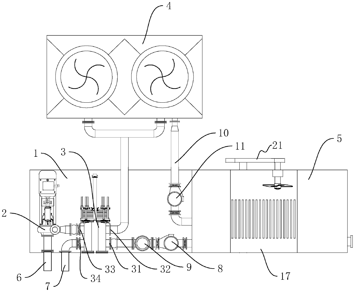
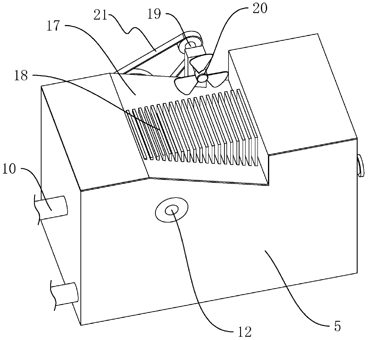
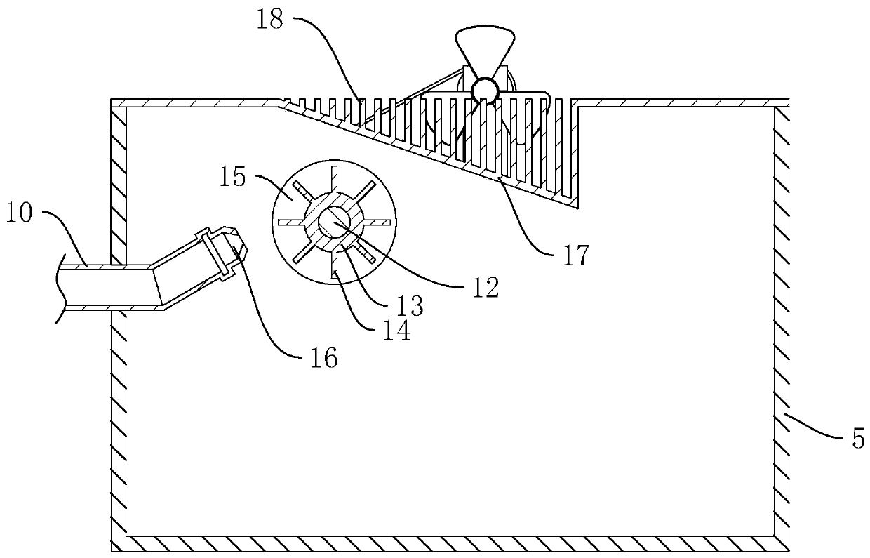
[0035] A mud cooling system such as figure 1 As shown, it includes an installation seat 1, a sand pump 2, a plate heat exchanger 3, a cooling water tower 4 and a water tank 5. Both the sand pump 2 and the plate heat exchanger 3 are located on the mounting base 1, and the water tank 5 is fixedly connected to the side of the mounting base 1. The plate heat exchanger 3 is a new type of high-efficiency heat exchanger formed by stacking a series of metal sheets with a certain corrugated shape. Thin rectangular channels are formed between the various plates to form a first fluid channel (not shown) and a second fluid channel (not shown). The first fluid channel is for cooling liquid to flow through, and the second fluid channel is for cooling Fluid passes through and heat is exchanged through the plates. The plate heat exchanger 3 includes a first fluid inlet 31 communicating with the first fluid channel, a first fluid outlet 32 ​​communicating with the first fluid channel and the...


PUM


Abstract

The invention discloses a mud cooling system and relates to the field of auxiliary equipment for well drilling. The mud cooling system comprises a sand pump, a plate heat exchanger, a cooling water tower and a water tank, wherein the plate heat exchanger comprises a first fluid inlet, a first fluid outlet, a second fluid inlet and a second fluid outlet; the first fluid outlet communicates with thefirst fluid inlet; the second fluid outlet communicates with the second fluid inlet; the output end of the sand pump is connected to the second fluid inlet; a discharging pipe is connected with the second fluid outlet; the water tank is connected to the first fluid inlet through a first water pump and used for guiding water into the plate heat exchanger; the first fluid outlet is connected to thecooling water tower; a water guiding pipe is connected between the cooling water tower and the water tank; a second water pump is connected onto the water guiding pipe; and the cooling water tower isused for conveying cooled water to the water tank through the second water pump. Through the arrangement of the sand pump, the plate heat exchanger, the cooling water tower and the water tank, the overall cooling efficiency can be higher and the cooling of hot mud can be further facilitated.

Description

technical field [0001] The invention relates to the field of drilling auxiliary equipment, more specifically, it relates to a mud cooling system. Background technique [0002] During the drilling process, the drilling tools can generate a lot of heat by cutting rocks, and at the same time, the friction between the drilling tools and the hole wall will generate a lot of heat, and as the drilling depth increases, the ground temperature at the bottom of the hole will gradually increase, and the heat will be transferred to the mud zone. out of the well. During this process, the temperature of the mud also gradually increases. The increase of the mud temperature will cause certain corrosion to the drilling tools and conveying equipment, shorten the service life of the drilling tools, and also affect the composition and function of the mud. Since both land drilling and oil drilling currently use mud configured according to geological conditions, the cost is relatively high, so mu...

Claims


Application Information

Patent Timeline
Patent Type & Authority Applications(China)
IPC IPC(8): F28C1/00F28D21/00F28F9/007F28F19/01E21B21/06
CPCE21B21/06F28C1/00F28C2001/006F28D21/00F28F9/007F28F19/01F28F2250/08
Inventor 王刚
Owner 陕西艾潽机械制造有限公司
Learn More