
A photonic lantern type degenerate module multiplexer/demultiplexer and transmission method

A demultiplexer and lantern-type technology, applied in the field of weakly coupled photon lantern degenerate mode group multiplexing and demultiplexing, can solve the problems of small area, low coupling efficiency of photodetectors, etc., achieve low crosstalk, solve Receiving problem of degenerate pattern group and effect of reducing production cost

Active Publication Date: 2021-02-09
PEKING UNIV +1
View PDF6 Cites 0 Cited by
  • Summary
  • Abstract
  • Description
  • Claims
  • Application Information

AI Technical Summary

Problems solved by technology

Secondly, because the light-receiving area of ​​the high-speed photodetector is small, the output pigtail of the few-mode photonic lantern is a few-mode fiber, and the numerical aperture is roughly the coupling efficiency with the photodetector.

Method used


Image

  • A photonic lantern type degenerate module multiplexer/demultiplexer and transmission method
  • A photonic lantern type degenerate module multiplexer/demultiplexer and transmission method
  • A photonic lantern type degenerate module multiplexer/demultiplexer and transmission method

Examples


Embodiment Construction

[0031] The present invention will be described in detail below by taking four LP mode high-selectivity photon lantern degenerate mode group multiplexers and demultiplexers as examples.

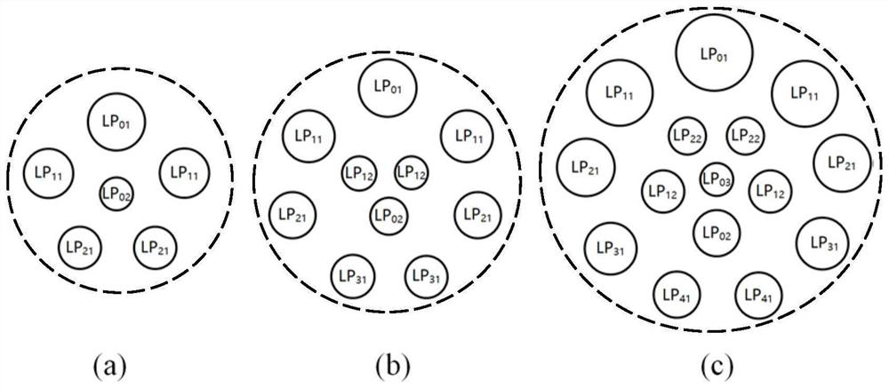
[0032] by figure 1 Design and process photon lantern multiplexer and demultiplexer by the fiber core arrangement method of four LP mode high selectivity photon lanterns. The end face of the fiber array of the multiplexer / demultiplexer is composed of six single-mode fibers, one of which is connected to the LP 01 mode corresponds to two roots with LP 11 mode corresponds to two roots with LP 21 mode corresponds to one with the LP 02 mode corresponds. The corresponding fiber core size relationship is LP 01 Mode > LP 11 Mode > LP 21 Mode > LP 02 model. Arrangement as figure 1 (a) shown. The thickness of the specific fiber core can be optimized through numerical simulation, and the processing of multiplexers and demultiplexers can be realized by the current fusion tapered process or femto...


PUM


Abstract

The invention discloses a photonic lantern type degenerate module multiplexing / demultiplexing device and a transmission method. The multiplexing / demultiplexing device structure of the present invention includes a plurality of fiber cores, wherein the thickness of the fiber cores transmitting different LP modes is different, and the degenerate modes in the same mode group adopt the same fiber core; the cross-section of the fiber core arrangement is axisymmetric, and the excited The core of the circular symmetric mode is on the symmetry axis, and the cores of the non-circular symmetric mode are symmetrically arranged on both sides of the axis; the cores are arranged in concentric rings to excite the LP pq The fiber core of the mode is located on the qth ring from the outside to the inside, and the fiber cores on both sides of each ring start from the fiber core on the axis of symmetry and are arranged in a progressively thinner manner; after the arrangement, one end of the fiber core is melted The tapering forms the tapered coupling region of the mux / demux. The invention solves the problem of degenerate mode group reception and has the advantages of wide working bandwidth and low crosstalk.

Description

technical field [0001] The invention relates to the design technology and application field of optical fiber passive devices, in particular to the design and application of a weakly coupled photonic lantern degenerate mode group multiplexing and demultiplexing device. Background technique [0002] In order to solve the problem of bandwidth shortage in single-mode optical fiber communication systems, mode-division multiplexing optical transmission schemes have been extensively studied. It utilizes orthogonal modes in few-mode / multi-mode fibers as independent channels for transmission, thus greatly increasing the spectral efficiency of optical communication systems. In a long-distance mode division multiplexing system, due to the strong crosstalk between modes, it is always necessary to use multiple-input multiple-output digital signal processing technology for channel equalization for all modes at the same time. For short-distance transmission scenarios such as data centers,...

Claims


Application Information

Patent Timeline
Patent Type & Authority Patents(China)
IPC IPC(8): G02B6/293G02B6/255H04J14/04
CPCG02B6/2552G02B6/2938H04J14/04
Inventor 李巨浩崔健高宇洋何永琪
Owner PEKING UNIV
Learn More