Rotor Pole Segmented Permanent Magnet Synchronous Motor and Its Electromagnetic Vibration Weakening Method

A technology for permanent magnet synchronous motors and rotor poles, applied to synchronous motors with stationary armatures and rotating magnets, synchronous machines, and parts of synchronous machines, which can solve the problem of weakening the cogging torque and torque ripple of permanent magnet motors Electromagnetic vibration, unfavorable motor high-precision control occasions, increased difficulty and cost of industrial manufacturing, etc., to achieve the effect of reducing electromagnetic vibration, reducing processing costs, and low processing costs

Active Publication Date: 2022-04-15
SHANDONG UNIV
View PDF3 Cites 0 Cited by
  • Summary
  • Abstract
  • Description
  • Claims
  • Application Information

AI Technical Summary

Problems solved by technology

[0007] However, surface-mounted permanent magnet motors also have the common disadvantages of permanent magnet motors, that is, cogging torque
The existence of cogging torque will increase the torque ripple of the permanent magnet motor, which is not conducive to the application of the motor in high-precision control occasions, and will bring additional electromagnetic vibration to the motor
At present, the method of stator skew or rotor skew is mainly used in industry to weaken the cogging torque, torque ripple and electromagnetic vibration of permanent magnet motors, but the way of skew or skew increases the difficulty and cost of industrial manufacturing. Difficult to achieve when the axial length of the motor is short

Method used


Image

  • Rotor Pole Segmented Permanent Magnet Synchronous Motor and Its Electromagnetic Vibration Weakening Method
  • Rotor Pole Segmented Permanent Magnet Synchronous Motor and Its Electromagnetic Vibration Weakening Method
  • Rotor Pole Segmented Permanent Magnet Synchronous Motor and Its Electromagnetic Vibration Weakening Method

Examples


Embodiment 1

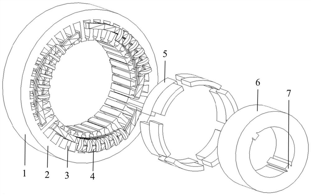
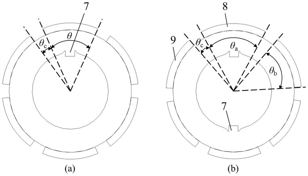
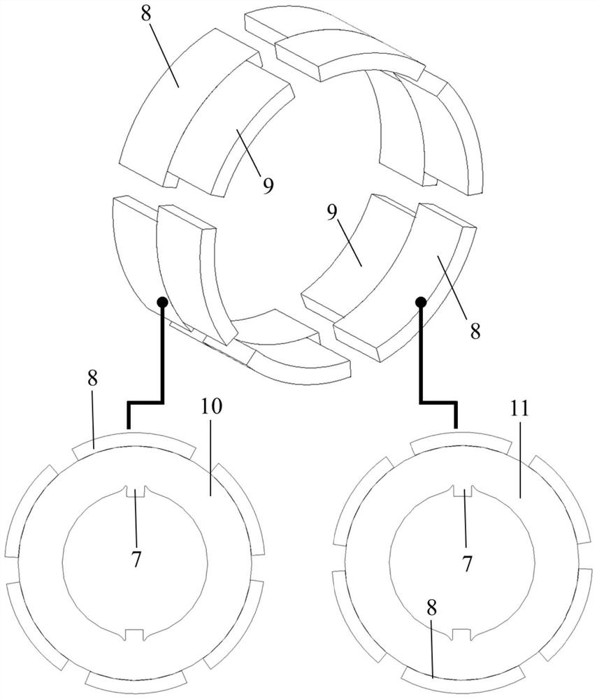
[0078] like Figure 1-Figure 8 As shown, the number of motor poles in this embodiment is 6, and the number of stator slots is 36. This embodiment includes a stator 1, permanent magnet rotors 10 and 11, and armature windings 4. The permanent magnet rotors 10 and 11 include a rotor core 6 and permanent magnet 5, the stator 1 is provided with a stator slot, the armature winding 4 is placed in the stator slot, the permanent magnet rotors 10 and 11 are arranged concentrically with the stator 1, and the permanent magnet rotor is divided into two parts along the axial direction. The two sections 10 and 11 have six permanent magnets 5 placed on the rotor surface of each section, and the pole arc width corresponding to one permanent magnet 8 in the six permanent magnets 5 is different from the pole arc width corresponding to the other permanent magnets 9 In this embodiment, the pole arc width corresponding to the permanent magnet 8 is greater than the pole arc width corresponding to th...

Embodiment 2

[0086] like Figure 9-Figure 16 As shown, the number of motor poles in this embodiment is 6, and the number of stator slots is 36. This embodiment includes a stator 1, permanent magnet rotors 10 and 11, and armature windings 4. The permanent magnet rotors 10 and 11 include a rotor core 6 and permanent magnet 5, the stator 1 is provided with a stator slot, the armature winding 4 is placed in the stator slot, the permanent magnet rotors 10 and 11 are arranged concentrically with the stator 1, and the permanent magnet rotor is divided into two parts along the axial direction. There are two sections 10 and 11, and six permanent magnets 5 are placed on the rotor surface of each section.

[0087] Among the six permanent magnets 5 , the pole arc width corresponding to one permanent magnet 8 is different from the pole arc width corresponding to the other permanent magnets 9 . In this embodiment, the pole arc width corresponding to the permanent magnet 8 is smaller than the pole arc w...


PUM


Abstract

The present invention provides a rotor pole segmented permanent magnet synchronous motor and its electromagnetic vibration weakening method, comprising a stator, a permanent magnet rotor and an armature winding, the permanent magnet rotor includes a rotor core and a permanent magnet, wherein the permanent The magnetic rotor is set inside the stator and arranged coaxially with the stator. The armature winding is arranged on the stator; the permanent magnet rotor is divided into two sections along the axial direction. For installation, 2p permanent magnets are placed on the surface of each section of the rotor, where p is the number of pole pairs of the motor. Among the permanent magnets, the pole arc width corresponding to one permanent magnet is different from the pole arc width corresponding to other permanent magnets. The other 2p‑1 permanent magnets have the same polar arc width. The invention can realize the suppression of the torque ripple and electromagnetic vibration of the surface-mounted permanent magnet motor under the condition of the non-inclined chute, and has low input cost.

Description

technical field [0001] The invention belongs to the technical field of electromagnetic vibration weakening, and relates to a rotor magnetic pole segmented permanent magnet synchronous motor and a method for reducing electromagnetic vibration. Background technique [0002] The statements in this section merely provide background information related to the present invention and do not necessarily constitute prior art. [0003] In recent years, with the improvement of high temperature resistance and price reduction of permanent magnet materials, permanent magnet motors have been widely used in national defense, industry, agriculture and daily life, and are moving towards high power, high functionality and miniaturization. With the development, the varieties and application fields of permanent magnet motors continue to expand. At present, the power of permanent magnet motors ranges from a few milliwatts to several thousand kilowatts, and their applications range from small toy ...

Claims


Application Information

Patent Timeline
Patent Type & Authority Patents(China)
IPC IPC(8): H02K1/278H02K1/16H02K21/14H02K21/02
CPCH02K1/278H02K1/165H02K21/14H02K21/029H02K2213/03
Inventor 王道涵彭晨
Owner SHANDONG UNIV
Why Eureka
Try Eureka