
Method, computer program product and computer system for correcting CT image

A technology of CT image and correction map, applied in the field of improving adaptive radiotherapy

Pending Publication Date: 2020-06-05
RAYSEARCH LAB
View PDF4 Cites 0 Cited by
  • Summary
  • Abstract
  • Description
  • Claims
  • Application Information

AI Technical Summary

Problems solved by technology

Moreover, the method is sensitive to noise and large artifacts

Method used


Image

  • Method, computer program product and computer system for correcting CT image
  • Method, computer program product and computer system for correcting CT image
  • Method, computer program product and computer system for correcting CT image

Examples


Embodiment Construction

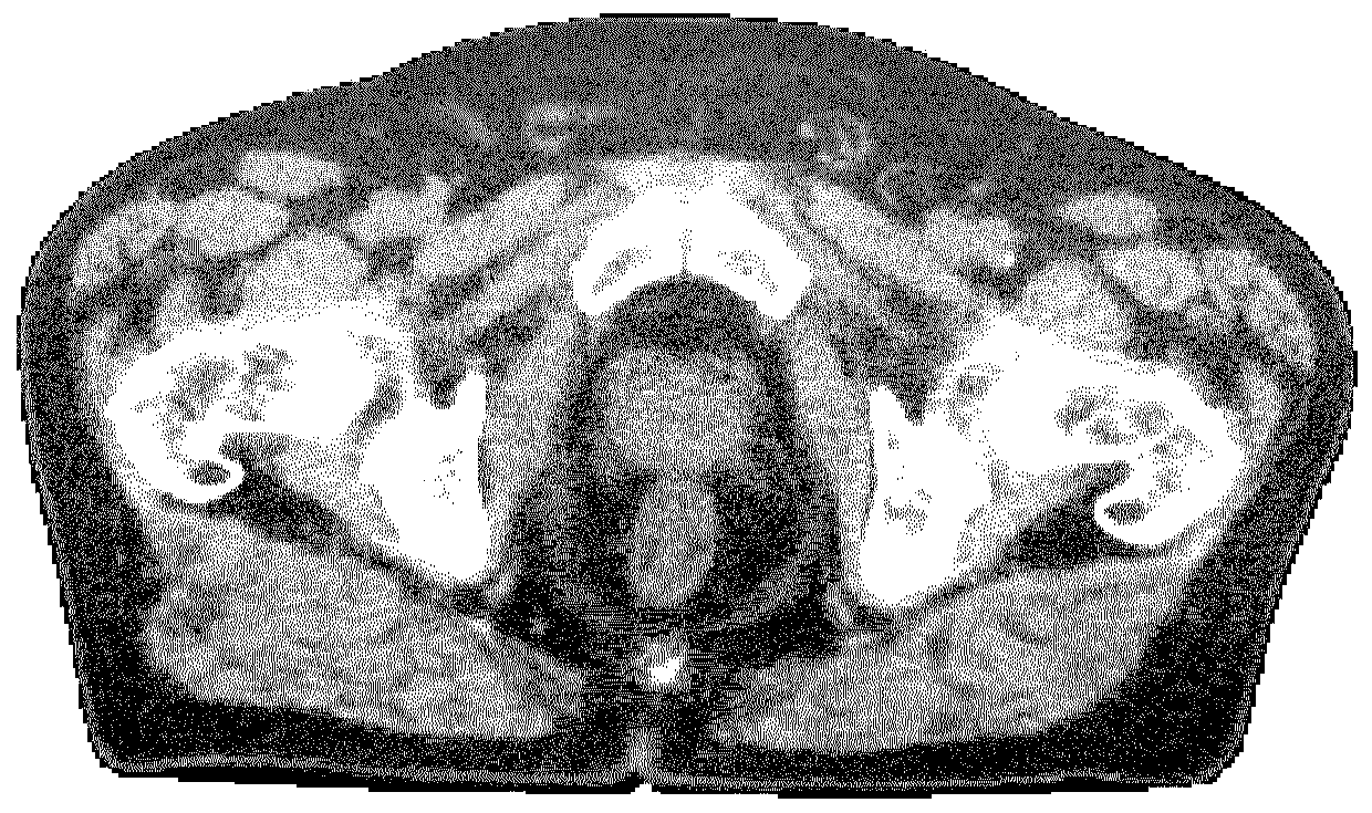
[0062] Figure 1a CT images are shown that may be used in aspects of the invention. Typically, CT images are obtained prior to treatment and used for treatment planning. As is common in the art, CT images express the attenuation coefficient of tissue in each voxel as Hounsfield Units (HU). The attenuation coefficient is related to density. Throughout the specification, density or electron density, or any suitable scale relating to either, may be used in place of Hounsfield units.

[0063] For simplicity and clarity, the following description is based on conversion between CBCT and CT. It should be understood that the image referred to as CBCT in the description may also be a CT image of any other type of CT modality. Typically, however, the image to be transformed and / or corrected has a lower quality, eg more occlusion artifacts, than the image used as reference in the correction and / or transformation.

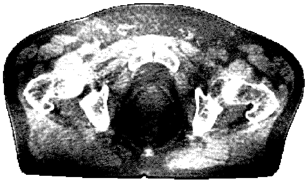
[0064] Figure 1b A CBCT image of the same region of the same patie...


PUM


Abstract

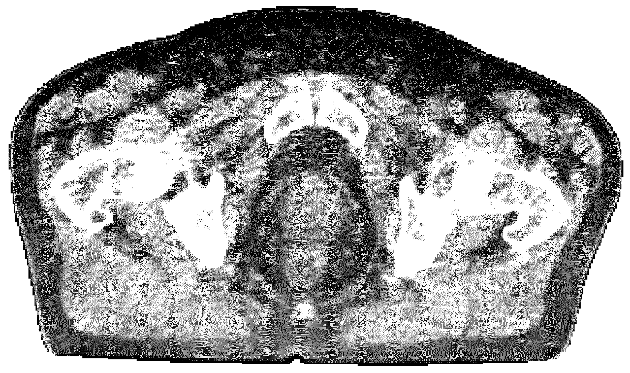
A method of correcting a first CT image for shading artefacts using another CT image as reference, comprising the steps of creating a difference image between the images and a correction map based onthe difference image. The correction map is used to correct the first CT image. A method of converting a CT image to the value range of another CT image is also disclosed.

Description

technical field [0001] The present invention relates to a method for improving adaptive radiotherapy and a computer program product and a computer system in which such a method can be implemented. Background technique [0002] In radiation therapy treatments, treatment is given in segments called fractions. Before treatment begins, a treatment plan to be used is generated based on high-resolution images, usually CT images. Before each section, new images, usually cone-beam CT (CBCT) images, are usually taken to ensure proper positioning of the patient. These images can also be used in adaptive radiotherapy, where the images are used to calculate the actual delivered dose (given up-to-date patient information). In order to be able to correlate the dose in the new image with the planned dose, the CBCT image is registered (preferably deformably) with the planned CT. CBCT images often have significant artifacts, which introduce errors in the calculated dose. Therefore, these...

Claims


Application Information

Patent Timeline
IPC IPC(8): G06T5/00G06T5/40G06T5/50
CPCG06T5/40G06T5/50G06T2207/10081G06T5/92G16H20/40G16H50/70G16H30/40G06F16/53A61B6/032A61B6/4085A61N5/1039G06T7/0014G06T11/008G06T2207/20224G06T2207/30008G06T2210/41G06T2211/424
Inventor 塞巴斯蒂安·安德森拉兹马斯·尼尔森埃里克·特拉内乌斯
Owner RAYSEARCH LAB
Learn More