Filter arrangement

A filter and dielectric material layer technology, applied in waveguide devices, resonators, linear waveguide feed arrays, etc., can solve the problems of far apart signals and signal integrity limitations, and achieve the effect of cost reduction

Active Publication Date: 2020-06-05
TELEFON AB LM ERICSSON (PUBL)
View PDF9 Cites 4 Cited by
  • Summary
  • Abstract
  • Description
  • Claims
  • Application Information

AI Technical Summary

Problems solved by technology

[0007] The signal integrity aspect also limits the possibilities because the signals cannot be separated very far and because it is difficult to fit a sufficient number of ground connections in the small cell defined by the antenna

Method used


Image

  • Filter arrangement
  • Filter arrangement
  • Filter arrangement

Examples


Embodiment Construction

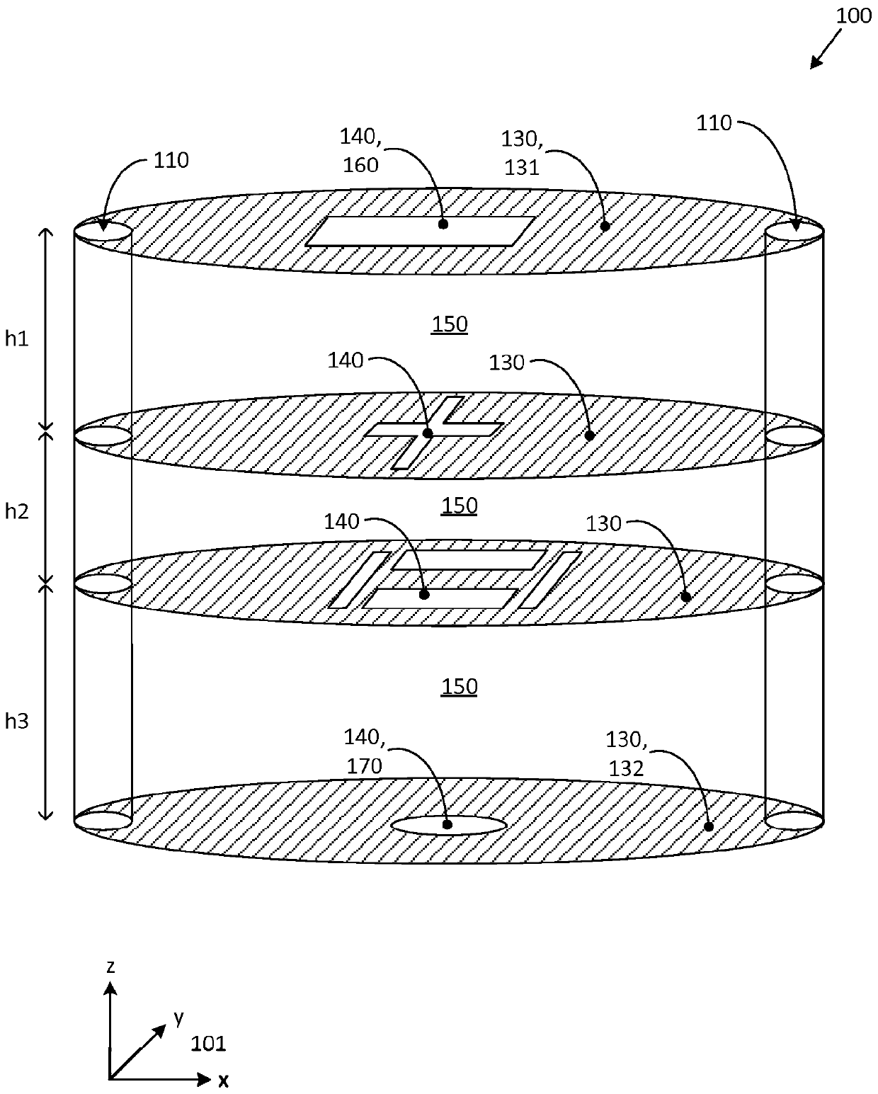
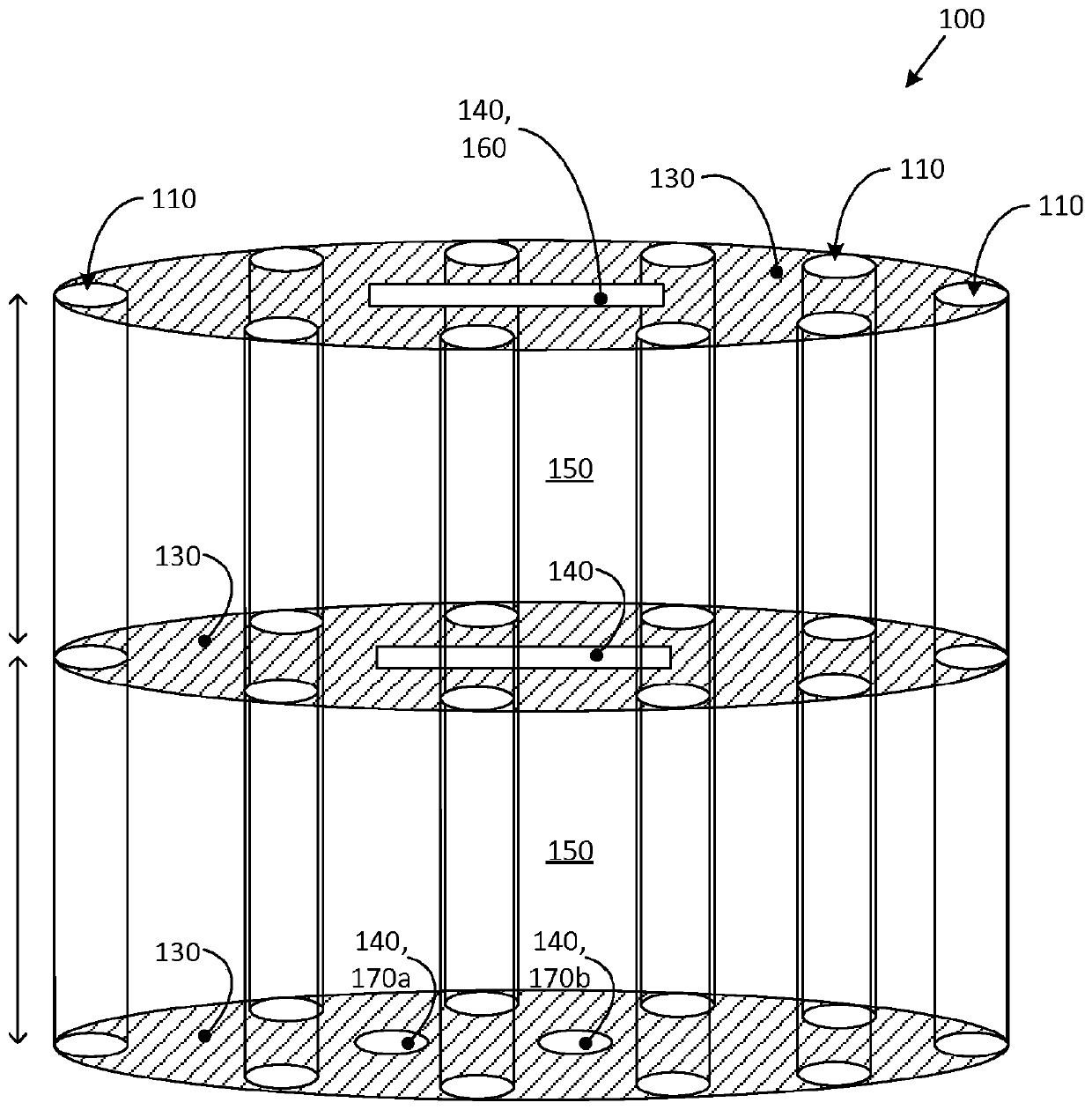
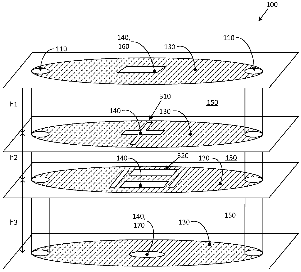
[0040] Using PCB technology, resonant cavities can be realized by electromagnetically shielding parts of the PCB. By connecting a number of such resonant cavities together by holes or openings in the shield, a filtering function can be obtained in the PCB material. The hole in the topmost metallization layer can be configured as an antenna element. In this way, the filter and antenna elements can be integrated and share the same footprint on the PCB.

[0041]In this paper an integrated filter-antenna arrangement is proposed which provides both filtering and broadband matching functions for the antenna unit. The resonator types used for the filters are substrate-integrated waveguides or substrate-integrated cavities for TE201 and TE102 modes. They have better Q factors and are less sensitive to manufacturing tolerances than traditionally designed components in filters for antenna functions. By using TE201 and TE102 degeneracy, it is also possible to support two orthogonal po...


PUM


Abstract

A filter arrangement comprising three or more stacked metallization layers separated by printed circuit board, PCB, layers. Each metallization layer comprises an aperture. The filter arrangement comprising a plurality of via-holes extending though the stacked metallization layers and through the separating Dielectric material layers, whereby the via-holes and the metallization layers delimit a cavity in each Dielectric material layer. The cavities in two consecutive Dielectric material layers being coupled by the aperture in the single metallization layer separating the two consecutive Dielectric material layers. The aperture of a topmost metallization layer being arranged as antenna element. The filter arrangement comprising a signal interface arranged as a conduit connecting at least onedielectric material layer to an exterior of the filter arrangement.

Description

technical field [0001] The present disclosure relates to a filter device having metallization layers separated by layers of dielectric material. The filter arrangement may be integrated with the antenna unit for use in a wireless device. Background technique [0002] An antenna unit is a device configured to transmit and / or receive electromagnetic signals, such as radio frequency (RF) signals for wireless communication. A phased antenna array is an antenna comprising multiple antenna elements whereby the antenna radiation pattern can be controlled by varying the relative phase and amplitude of the signals fed back to the different antenna elements. [0003] The practical implementation of the signal filtering function of such an antenna unit is a challenging task. A high Q value, multiple resonators, and high precision are required to realize a filter with low loss and strong rejection of frequencies near the operating band where radio frequency (RF) power interference or ...

Claims


Application Information

Patent Timeline
Patent Type & Authority Applications(China)
IPC IPC(8): H01P1/208
CPCH01P1/208H01P1/2088H01P7/06H01Q15/24H01Q19/005H01Q21/005
Inventor A·德莱尼夫O·塔格曼
Owner TELEFON AB LM ERICSSON (PUBL)
Why Eureka
Try Eureka