Hydro-pneumatic suspension system, position detection method thereof and engineering vehicle

A technology of oil-pneumatic suspension and suspension cylinder, which is applied to vehicle components, suspensions, elastic suspensions, etc., can solve the problems of high cost, low maintenance efficiency, and inconvenient maintenance, so as to reduce production cost and maintenance cost, and reduce maintenance difficulty , Improve the effect of maintenance efficiency

Inactive Publication Date: 2020-06-09
SANY AUTOMOBILE HOISTING MACHINERY
View PDF6 Cites 4 Cited by
  • Summary
  • Abstract
  • Description
  • Claims
  • Application Information

AI Technical Summary

Problems solved by technology

[0005] The object of the present invention is to provide a kind of oil-pneumatic suspension system and its position detection method and engineering vehicle, to alleviate the position detection method of the existing oil-pneumatic suspension system, when the sensor fails, it needs to dismantle the suspension oil cylinder to repair and replace the sensor or replace the suspension. Oil cylinder assembly, technical problems of inconvenient maintenance, low maintenance efficiency and high cost

Method used


Image

  • Hydro-pneumatic suspension system, position detection method thereof and engineering vehicle
  • Hydro-pneumatic suspension system, position detection method thereof and engineering vehicle
  • Hydro-pneumatic suspension system, position detection method thereof and engineering vehicle

Examples


Embodiment 1

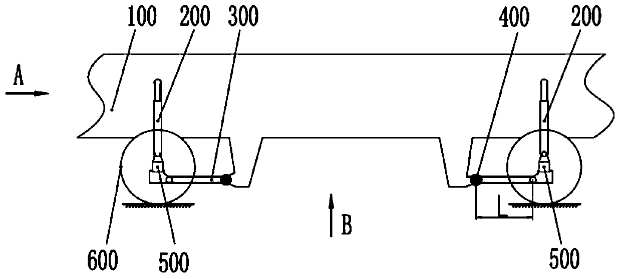
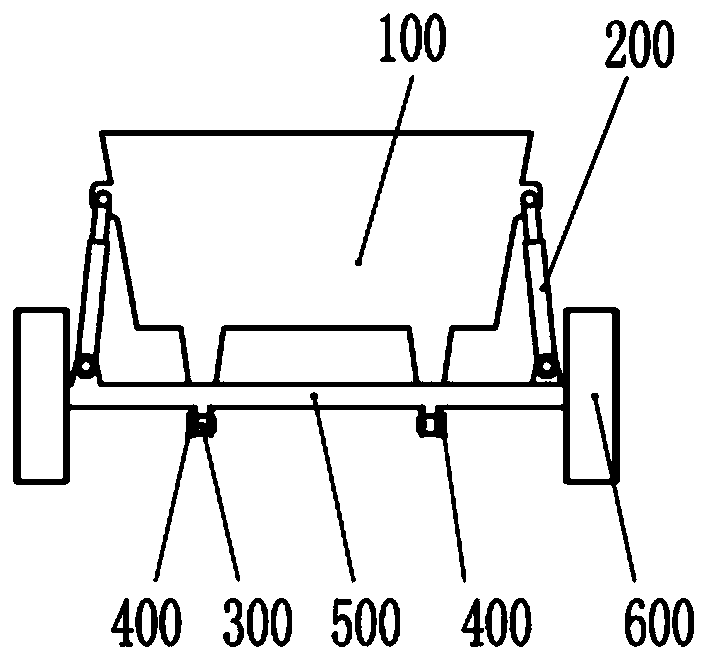
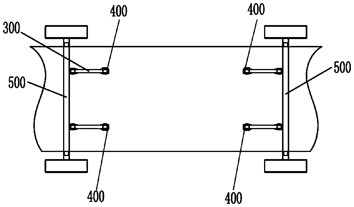
[0040] Such as Figure 1-Figure 4 As shown, the hydropneumatic suspension system provided by the present invention includes a vehicle frame 100 , an axle 500 , a suspension cylinder 200 , a thrust rod 300 and a rotation angle sensor 400 .

[0041] The vehicle frame 100 and the vehicle axle 500 are connected through the suspension cylinder 200, one end of the suspension cylinder 200 is connected to the vehicle frame 100, and the other end is connected to the vehicle axle 500, when the suspension cylinder 200 stretches, it can Realize that the frame 100 moves in the erecting direction relative to the axle 500 .

[0042] One end of the thrust rod 300 is connected to the vehicle frame 100 , and the other end of the thrust rod 300 is connected to the axle 500 .

[0043] The rotation angle sensor 400 is used to detect the rotation angle of the thrust rod 300 relative to the initial position, and according to the rotation angle, the suspension state of the oil-pneumatic suspension s...

Embodiment 2

[0055] Such as Figure 5 As shown, the difference from Embodiment 1 is that further, the rotation angle sensor 400 is arranged at the hinge of the thrust rod 300 and the axle 500 .

[0056] Specifically, in the present embodiment, the rotation angle sensor 400 is installed at the joint joint of the axle 500 and the thrust rod 300 . The fixed part of the rotation angle sensor 400 is fixedly connected with the vehicle axle 500 , and the rotating part of the rotation angle sensor 400 is fixedly connected with the thrust rod 300 . When the suspension cylinder 200 expands and contracts, when the vehicle frame 100 moves up and down, it drives one end of the thrust rod 300 connected to the axle 500 to move. 300 will rotate relative to the hinge point of thrust rod 300 and vehicle frame 100, thereby generating angular displacement. At this time, the angular displacement and rotation angle data of the thrust rod 300 can be detected by the rotation angle sensor 400, and the mutual pos...

Embodiment 3

[0058] Such as Figure 6 , Figure 7 As shown, the difference from Embodiment 1 is that, further, the hydropneumatic suspension system includes an auxiliary rod 700; one end of the auxiliary rod 700 is hinged to the axle 500, and the other end is connected to the vehicle frame 100. .

[0059] The rotation angle sensor 400 is arranged on the auxiliary rod 700 for detecting the swing angle of the auxiliary rod 700, and according to the swing angle, obtains the suspension state of the oil-pneumatic suspension system.

[0060] Further, the rotation angle sensor 400 is arranged at the hinge of the auxiliary rod 700 and the vehicle frame 100 .

[0061] Specifically, in this embodiment, an auxiliary rod 700 is arranged between the vehicle frame 100 and the axle 500, the auxiliary rod 700 can be arranged at the middle position of the two wheels, and the rotation angle sensor 400 is arranged between the auxiliary rod 700 and the vehicle axle. The hinge of the frame 100 , that is, th...


PUM


Abstract

The invention provides a hydro-pneumatic suspension system, a position detection method thereof and an engineering vehicle, and relates to the technical field of engineering machinery. The hydro-pneumatic suspension system provided by the invention comprises a frame, an axle, a suspension oil cylinder, a thrust rod and a rotation angle sensor; wherein the frame is connected to the axle through thesuspension oil cylinder, one end of the thrust rod is connected to the frame, and the other end of the thrust rod is connected to the axle; the rotation angle sensor is used for detecting a rotationangle of the thrust rod relative to an initial position and acquiring the suspension state of the hydro-pneumatic suspension system according to the rotation angle. The rotation angle of the thrust rod relative to the initial position is detected through the rotation angle sensor, and the position state of the hydro-pneumatic suspension system is obtained according to the rotation angle, so that the production cost and the maintenance cost in position detection of the hydro-pneumatic suspension system of the vehicle are reduced, the maintenance difficulty is reduced, and the maintenance efficiency is improved.

Description

technical field [0001] The invention relates to the technical field of engineering machinery, in particular to an oil-air suspension system, a position detection method thereof, and an engineering vehicle. Background technique [0002] For vehicles with oil-pneumatic suspension systems, in order to realize accurate control of the vehicle suspension system, it is necessary to detect the position of the vehicle suspension system. [0003] The position detection of the traditional oil-air suspension system is to use the linear distance position sensor to directly detect the position of the suspension system. This method must use a linear position sensor, which must be arranged on the linear displacement components of the oil-air suspension system. Generally, the distance sensor is built into the suspension cylinder. [0004] In this way, when the sensor fails, it is necessary to disassemble the suspension oil cylinder for maintenance and replacement of the sensor or the suspen...

Claims


Application Information

Patent Timeline
Patent Type & Authority Applications(China)
IPC IPC(8): B60G13/06B60G17/019G01B21/22
CPCB60G13/06B60G17/019G01B21/22
Inventor 安术军杨尚峰黎晓强
Owner SANY AUTOMOBILE HOISTING MACHINERY
Why Eureka
Try Eureka