Practical charging pile for new energy automobile

A technology for new energy vehicles and charging piles, applied in electric vehicle charging technology, charging stations, electric vehicles, etc., can solve the problems of limited battery capacity and lack of supplementary power for electric vehicles, and achieve increased coverage, convenient use, and prevention of overheating effect

Inactive Publication Date: 2020-06-09
张和平
View PDF0 Cites 1 Cited by
  • Summary
  • Abstract
  • Description
  • Claims
  • Application Information

AI Technical Summary

Problems solved by technology

[0003] In our country, new energy vehicles are mostly driven by electricity. Now, new energy vehicles using electricity as energy have begun to be put into the market. However, the battery capacity of electric vehicles is extremely limited, and they lack a facility to effectively supplement electricity. A convenient and practical charging facility for new energy vehicles that is easy to popularize. Therefore, a practical charging pile for new energy vehicles is now provided

Method used


Image

  • Practical charging pile for new energy automobile
  • Practical charging pile for new energy automobile
  • Practical charging pile for new energy automobile

Examples


Embodiment 1

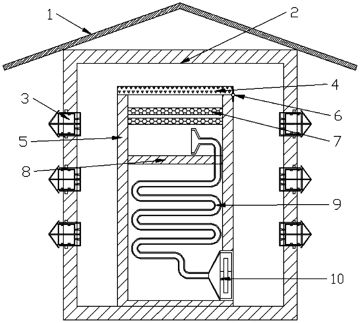
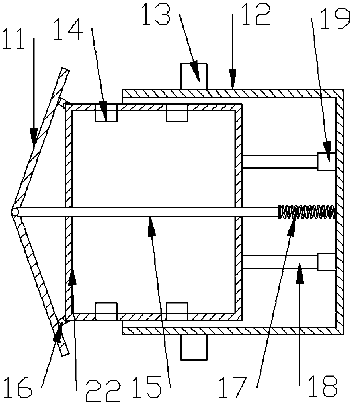
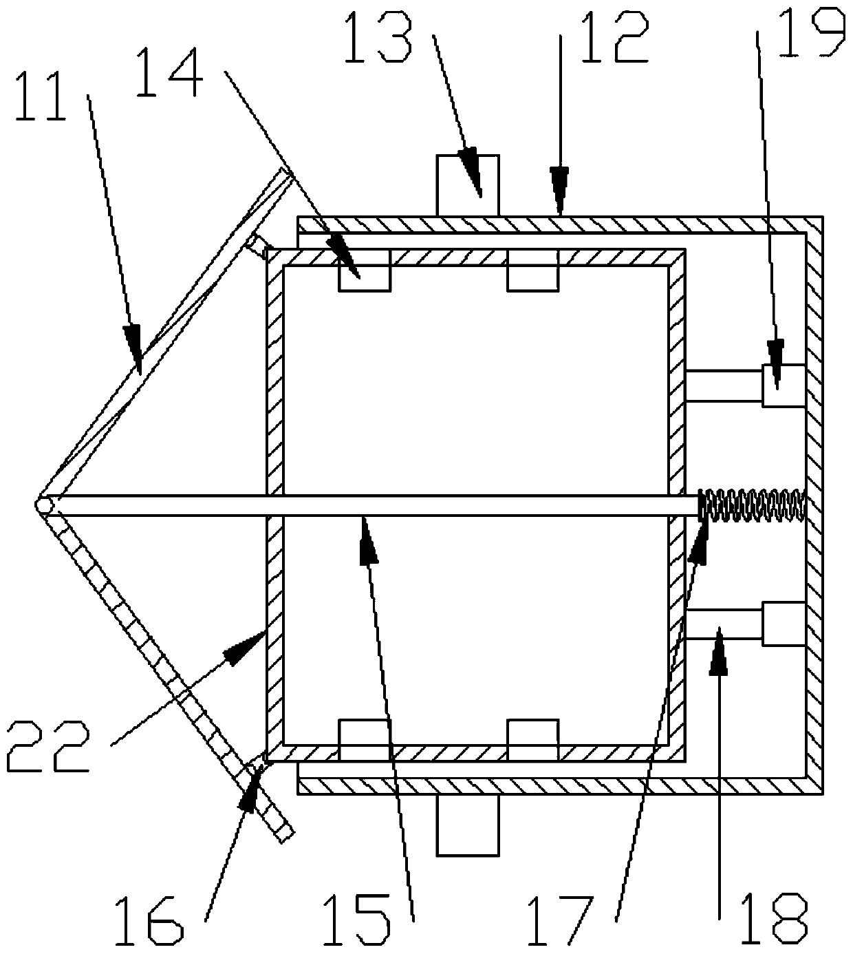
[0023] see Figure 1-4 , this embodiment provides a practical charging pile for new energy vehicles, including a large cover 1 and a main casing 2, the top of the main casing 2 is provided with a large cover 1, and the cross-section of the large cover 1 In the shape of "∧", several charging bins 3 are arranged on the side of the main casing 2. The charging bin 3 includes an outer casing 12, and an inner casing 22 is arranged inside the outer casing 12. On the inner casing 22 At least one charging hole 14 is provided on the side, and a telescopic mechanism 19 is also provided in the outer casing 12, and the end of the telescopic mechanism 19 away from the outer casing 12 is slidably connected with a piston rod 18, and the piston rod 18 is far away from the One end of the telescoping mechanism 19 is connected to the inner casing 22, and a small cover plate 11 is also provided. The cross section of the small cover plate 11 is "<" shaped, and the middle position of the small cover...

Embodiment 2

[0032]On the basis of Embodiment 1, the charging compartment 3 and the main casing 2 are movable, and the outer casing 2 is provided with a round hole on the side wall, and the side wall of the round hole is provided with a snap-in groove. 20, the clamping groove 20 is in the shape of "∟", the outer shell 12 is arranged in the circular hole and the clamping column 13 is arranged on it. A stop piece 21 is arranged on the fastening post 13 , and the stop piece 21 is arc-shaped. In this way, the clamping of the charging compartment 3 can be realized through the clamping groove 20 and the clamping column 13, and the disassembly and assembly are convenient, and the stop piece 21 tends to be in an open state. When the column 13 is located in the clamping groove 20, the stop piece 21 can provide a certain resistance, so that the charging compartment 3 is more stable in the circular hole, so that the charging compartment 3 can be taken out, so that the device The coverage area is gre...


PUM


Abstract

The invention discloses a practical charging pile for a new energy automobile, and relates to the field of new energy vehicles. A large cover plate is arranged, so sun-shading and rain-shielding effects are achieved; a photovoltaic panel is arranged on the large cover plate, and can utilize solar energy to achieve energy-saving and environment-friendly effects; a structure similar to an umbrella is formed among a small cover plate, a thin support rod and an inner shell, and when the structure is not in use, the protective effect can be achieved; a cooling cavity is arranged, so air is cooled under the action of a cooling liquid after passing through a coil pipe in the cooling cavity, the cooled air is discharged into a main shell, and the whole charging pile can be cooled to prevent overheating; a filtering layer is arranged, so air in the charging file can be filtered and dedusted through the filtering layer to prevent the performances of the charging file from being affected by dusts; and a charging bin and the main shell are movably connected in a clamped mode, so the charging bin can be taken out, the coverage range of the charging pile is greatly enlarged, and use is more convenient.

Description

technical field [0001] The invention relates to the technical field of new energy vehicles, in particular to a practical charging pile for new energy vehicles. Background technique [0002] Cars are a means of transportation. With the development of the times and the improvement of the economic level, more and more people own and drive cars for travel. However, most of the existing cars use oil as energy. In this way, cars will emit a lot of With the increasing pollution of automobile exhaust, the demand for new energy vehicles is increasing. New energy vehicles refer to the use of unconventional vehicle fuels as power sources (or conventional vehicle fuels, new vehicle power devices) ), comprehensive vehicle power control and advanced technology in driving, and form vehicles with advanced technical principles, new technologies and new structures. New energy vehicles include pure electric vehicles, extended-range electric vehicles, hybrid vehicles, and fuel cell electric veh...

Claims


Application Information

Patent Timeline
Patent Type & Authority Applications(China)
IPC IPC(8): B60L53/31B60L53/302B01D46/00
CPCB01D46/00B01D2258/06B60L53/302B60L53/31Y02T10/70Y02T10/7072Y02T90/12
Inventor 张和平
Owner 张和平
Why Eureka
Try Eureka