Burner for gas stove

A technology for burners and gas stoves, which is applied in the direction of gas fuel burners, burners, and incombustible liquid/gas transportation, etc. It can solve the problems of wasting gas, inability to conduct uniform heat, and poor combustion efficiency, and achieve uniform flow rate and increase in Combustion efficiency and heat load improvement effect

Inactive Publication Date: 2020-06-09
NINGBO FOTILE KITCHEN WARE CO LTD
View PDF10 Cites 2 Cited by
  • Summary
  • Abstract
  • Description
  • Claims
  • Application Information

AI Technical Summary

Problems solved by technology

[0002] At present, the burners of common gas stoves on the market can be roughly divided into two types: the outer flame burner and the inner flame burner. Because the flame generated by the outer flame burner is often prone to sparks, resulting in uneven Heat conduction and combustion efficiency are poor, so there are disadvantages such as waste of gas and long cooking time; while the flame produced by the internal flame type stove does not have flames, because it can be concentrated inward, so the combustion efficiency can be improved, but the internal flame type burner head The flame is concentrated in the central part, and the effect of uniform distribution of the flame cannot be achieved
In addition, both the outer flame burner and the inner flame burner belong to the secondary combustion structure, and the secondary combustion requires more air to completely burn the intermediate products after the primary combustion. In addition, the burner structure of the secondary combustion is usually provided with an inner ring and an outer ring, and the inner and outer rings must be covered with oblique flame holes. Therefore, the burner head of the secondary combustion has Disadvantages of complex structure and difficult processing

Method used


Image

  • Burner for gas stove
  • Burner for gas stove
  • Burner for gas stove

Examples


Embodiment 2

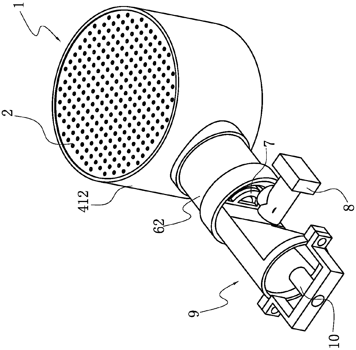
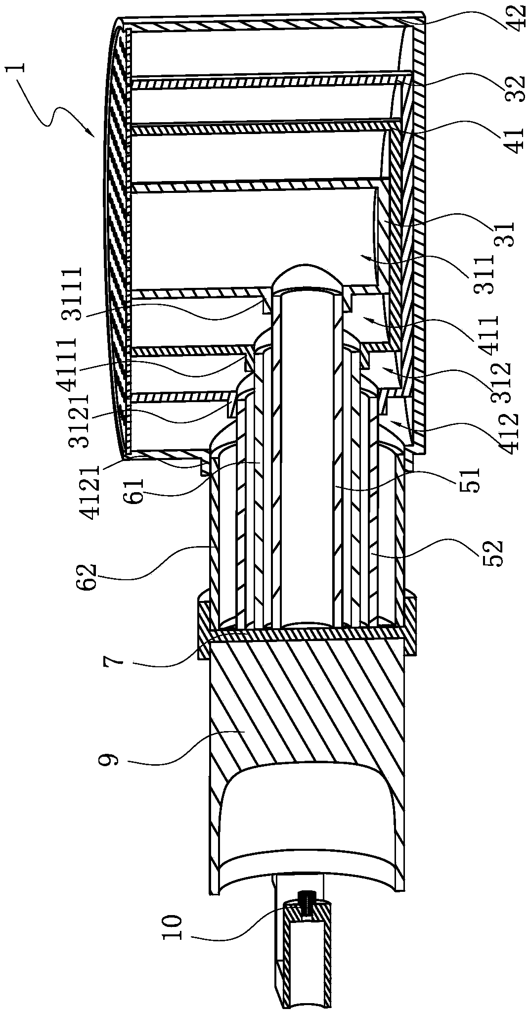
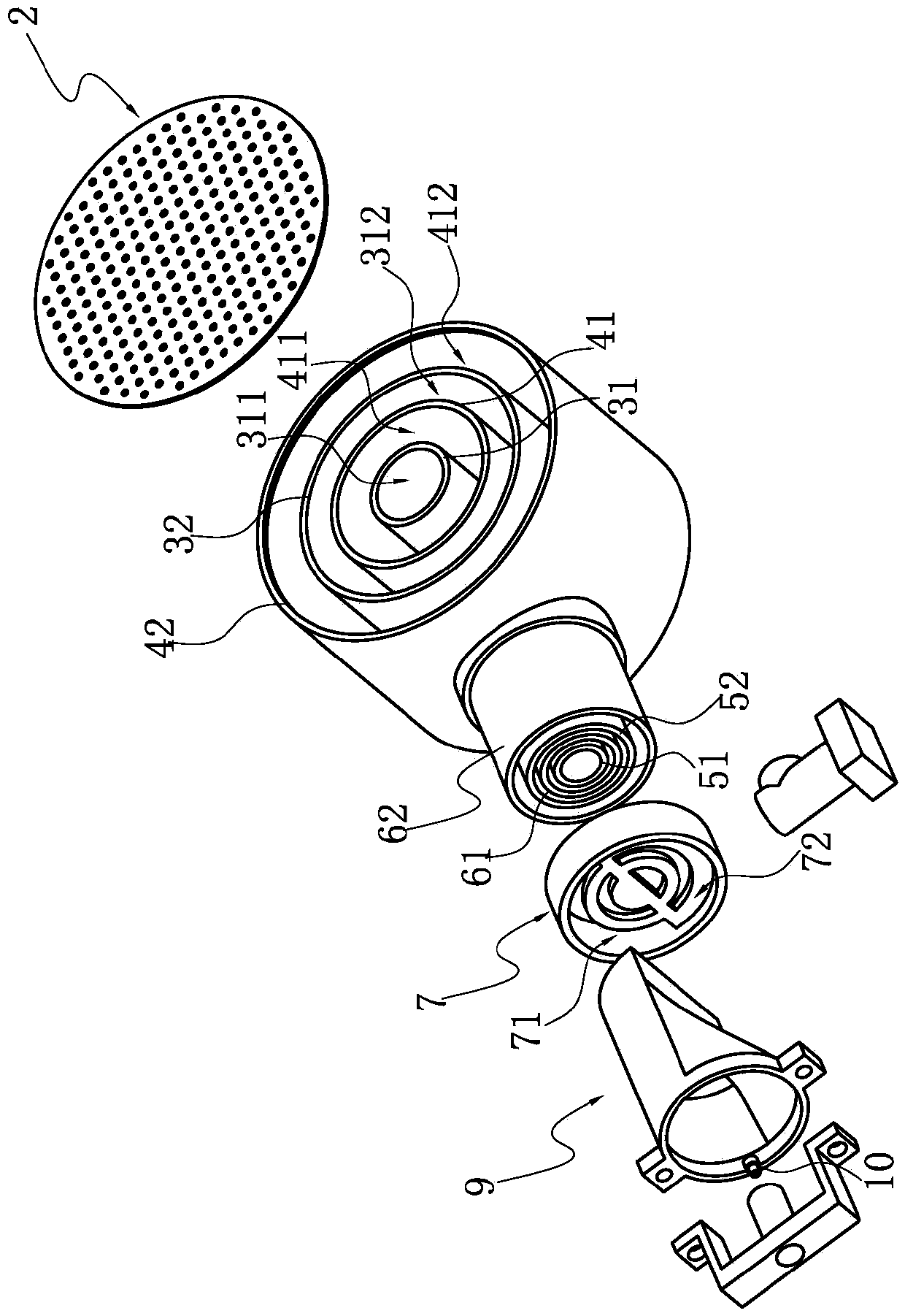
[0032] The structure is basically the same as that of Embodiment 1, the only difference is that the first air pipe 51 and the second air pipe 52 are located on one side of the burner body 1, wherein the second air pipe 52 is arranged around the first air pipe 51, and the first The air pipe 51 is arranged transversely through the peripheral gas chamber 412, and the second air pipe 52 communicates with the first air pipe 51 and is connected with the air supply part 8 such as a blower, so that air can enter the peripheral air chamber 312 and the central air chamber 311; The gas pipe 61 and the second gas pipe 62 are located on the other side of the burner body 1, wherein the second gas pipe 62 is arranged around the first gas pipe 61, the first gas pipe 61 is arranged transversely through the peripheral air chamber 312, and the second gas pipe The pipe 62 is connected with the injection pipe 9 and the nozzle 10 together with the first gas pipe 61, so that the gas enters the periph...


PUM


Abstract

The invention relates to a burner for a gas stove. The burner comprises a burner body provided with at least two gas chambers, a gas pipe communicating with the gas chambers, and a mesh type fire cover covering the opening part of the burner body; the burner is characterized in that the at least two gas chambers are sequentially distributed from the center to the periphery at an interval, and an air chamber is formed in the interval; the burner further comprises an air pipe; and the air pipe communicates with the air chamber. Compared with the prior art, the burner has the following advantages: the burner enables flames to be uniformly scattered on the mesh type fire cover to form short flames; and the flames are unlikely to jump to improve the combustion efficiency, so that the gas is enabled to be distributed at all parts of the gas chambers more uniformly on one hand to enable the flow rate of gas reaching a fire hole to be more uniform.

Description

technical field [0001] The invention relates to a burner for a gas stove, in particular to a burner for a gas stove. Background technique [0002] At present, the burners of common gas stoves on the market can be roughly divided into two types: the outer flame burner and the inner flame burner. Because the flame generated by the outer flame burner is often prone to sparks, resulting in uneven Heat conduction and combustion efficiency are poor, so there are disadvantages such as waste of gas and long cooking time; while the flame produced by the internal flame type stove does not have flames, because it can be concentrated inward, so the combustion efficiency can be improved, but the internal flame type burner head The flame is concentrated in the central part, and the effect of uniform distribution of the flame cannot be achieved. In addition, both the outer flame burner and the inner flame burner belong to the secondary combustion structure, and the secondary combustion re...

Claims


Application Information

Patent Timeline
Patent Type & Authority Applications(China)
IPC IPC(8): F23D14/04F23D14/46F23D14/58F23D14/64F23L9/00
CPCF23D14/04F23D14/46F23D14/58F23D14/64F23D2900/14062F23L9/00
Inventor 苏慧玲
Owner NINGBO FOTILE KITCHEN WARE CO LTD
Why Eureka
Try Eureka