
Energy harvesting mechanism for range hood and oil cup liquid level detection device applying same

A range hood, energy capture technology, applied in the application, removal of oil fume, circuit devices and other directions, can solve the problems of increasing the total energy consumption of the range hood, increasing the cleaning difficulty of the range hood, spilling dirty oil, etc., so as to improve the utilization of energy. rate effect

Active Publication Date: 2020-06-09
NINGBO FOTILE KITCHEN WARE CO LTD
View PDF11 Cites 0 Cited by
  • Summary
  • Abstract
  • Description
  • Claims
  • Application Information

AI Technical Summary

Problems solved by technology

However, the current sensors used in the range hood are powered by a power supply, which will increase the total energy consumption of the range hood accordingly.
[0005] In addition, currently used range hoods rarely have components for detecting the liquid level of the oil cup, and users often do not pay attention to the height of the liquid level in the oil cup during the use of the range hood. If you forget to clean the oil cup and the dirty oil overflows, it will increase the difficulty of cleaning the range hood

Method used


Image

  • Energy harvesting mechanism for range hood and oil cup liquid level detection device applying same
  • Energy harvesting mechanism for range hood and oil cup liquid level detection device applying same
  • Energy harvesting mechanism for range hood and oil cup liquid level detection device applying same

Examples


Embodiment Construction

[0029] The present invention will be described in further detail below in conjunction with the embodiments of the drawings.

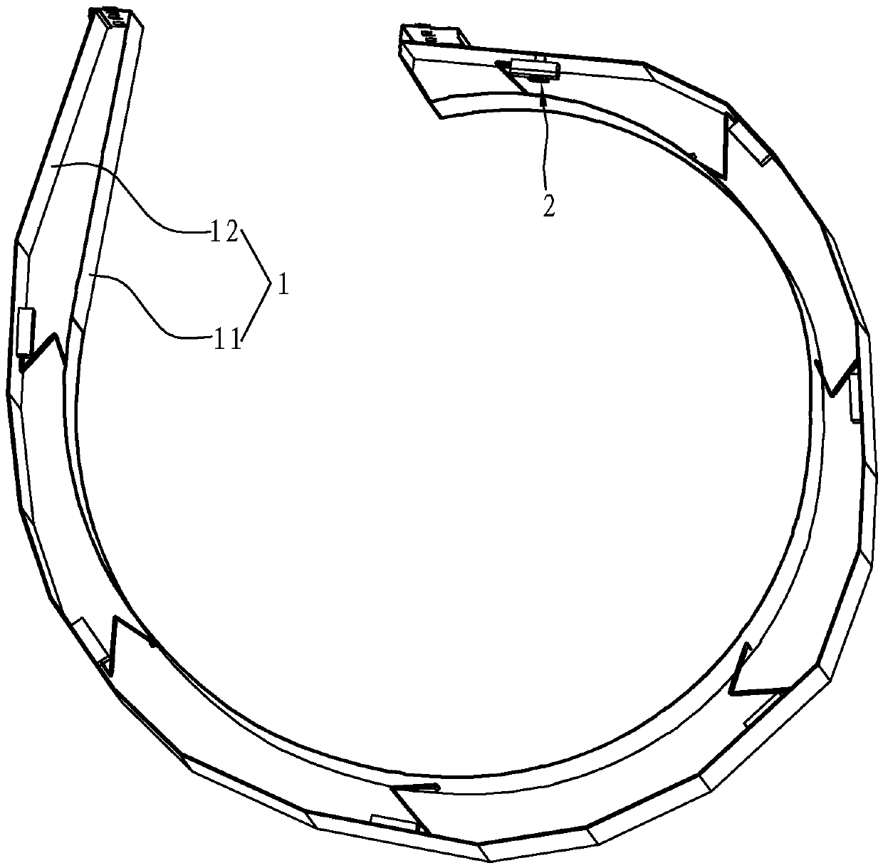
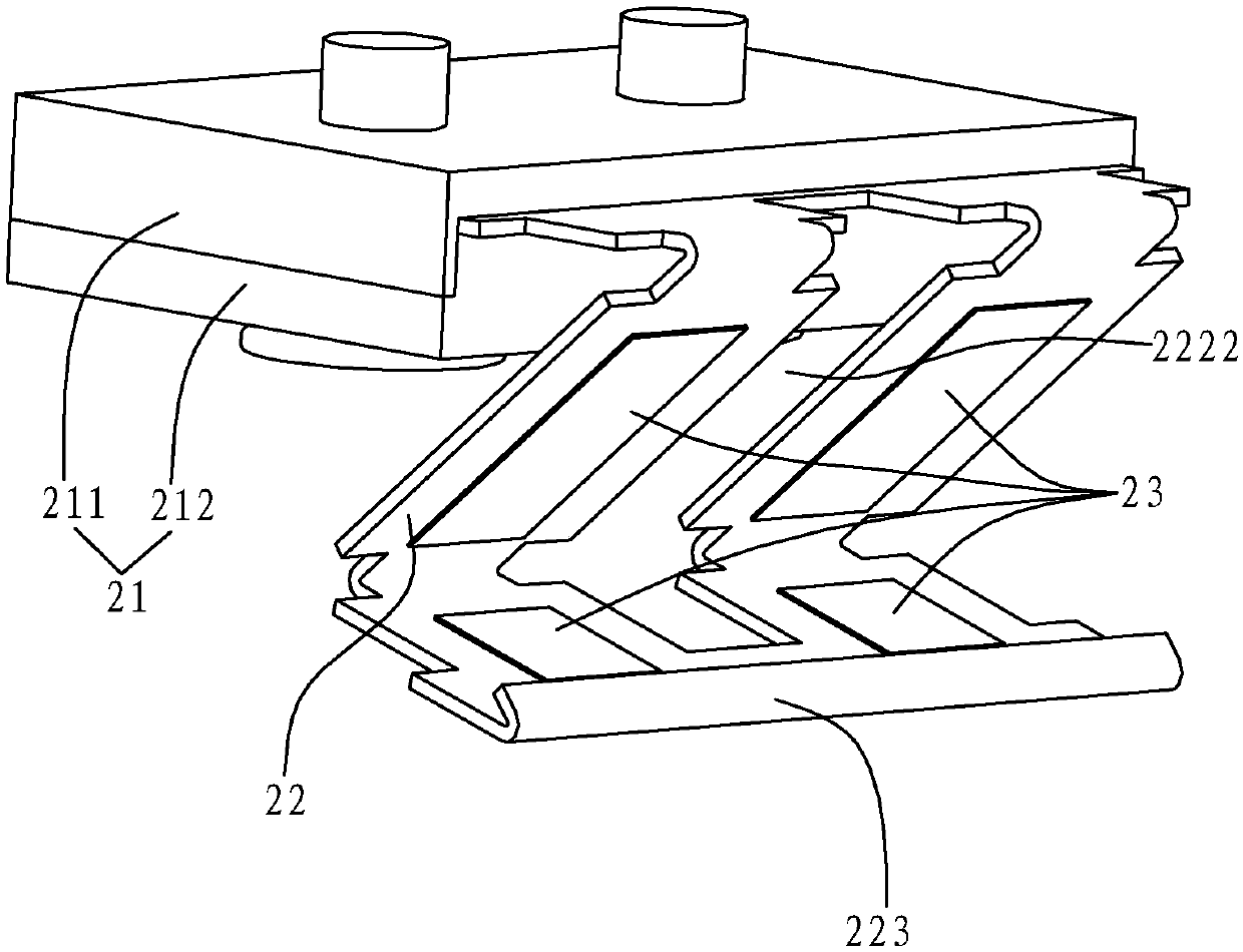
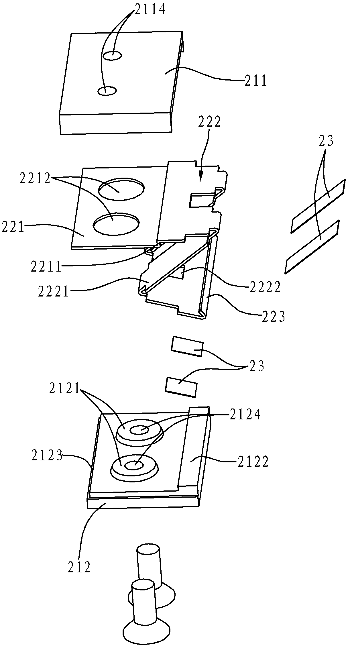
[0030] Such as Figure 1 to Figure 4 As shown, the energy capture mechanism for a range hood in this embodiment includes a housing 1, a plurality of energy capture elements 2 arranged in the housing 1, and an electric storage module 3 electrically connected to each energy capture element 2.

[0031] The housing 1 includes an inner ring shell 11 and an outer ring shell 12, wherein the inner ring shell 11 is closely attached to the outer ring wall of the volute, and both ends of the inner ring shell 11 are equipped with installations that can be adapted to be installed on other components. surface. The outer ring shell 12 is surrounded by the inner ring shell 11. The inner ring shell 11 in this embodiment is composed of multiple planes continuously and integrally arranged in the circumferential direction according to the change of the curvature angle of the v...


PUM


Abstract

The invention relates to an energy harvesting mechanism for a range hood. The energy harvesting mechanism comprises a shell, at least three energy harvesting elements and a power storage module, wherein the shell is arranged outside a ring wall of a volute in an enclosing way; the at least three energy harvesting elements are arranged in the shell at intervals along a circumferential direction; the power storage module is electrically connected with each energy harvesting element; the shell comprises an inner ring shell attached to the outside of the volute and an outer ring shell arranged outside the inner ring shell in an enclosing way; the outer ring shell is connected with the inner ring shell; one end of each energy harvesting element is fixed to an inner surface of the outer ring shell; and the other end of each energy harvesting element can be movably pressed against an inner surface of the inner ring shell. The energy harvesting mechanism for the range hood disclosed by the invention is arranged on the periphery of the volute, and can harvest energy lost during the vibration of the volute, so that energy recovery is realized; the energy utilization rate of the range hood can be improved; energy is saved; and environmental protection is facilitated. The invention also discloses an oil cup liquid level detection device. The oil cup liquid level detection device comprisesthe energy harvesting mechanism, and a liquid level sensor which is electrically connected with the power storage module in the energy harvesting mechanism and is used for detecting the oil cup liquidlevel. The oil cup liquid level detection device is more user-friendly.

Description

Technical field [0001] The invention relates to the technical field of range hoods, in particular to an energy capture mechanism for range hoods, and also relates to an oil cup liquid level detection device applying the energy capture mechanism for range hoods. Background technique [0002] The range hood will vibrate during operation, especially in the fan system, part of its energy is wasted by the vibration of the volute. For the current vibration problems in range hoods, corresponding measures are mainly taken to reduce vibration or avoid transmission of vibration. However, the current range hood does not make full use of the vibration energy, and the utilization rate of the reusable vibration energy is low, and the energy consumption of the corresponding range hood is also large. [0003] For example, the Chinese utility model patent "Range Hood" with the authorized announcement number CN202546882U (application number CN2012201046156.7), in the range hood disclosed therein, t...

Claims


Application Information

Patent Timeline
Patent Type & Authority Applications(China)
IPC IPC(8): F24C15/20H02J7/32
CPCF24C15/20F24C15/2021H02J7/32
Inventor 何海浪任树栋
Owner NINGBO FOTILE KITCHEN WARE CO LTD
Learn More