

Hydraulic pushing and inclining mechanism for automatic feeder of submerged arc furnace
A technology of automatic feeding and submerged arc furnace, which is applied in the charging process of submerged arc furnace and the field of metallurgy to achieve the effect of prolonging service life, large torque and efficient use of space
- Summary
- Abstract
- Description
- Claims
- Application Information
AI Technical Summary
Problems solved by technology
Method used
Image

Examples
Embodiment 1
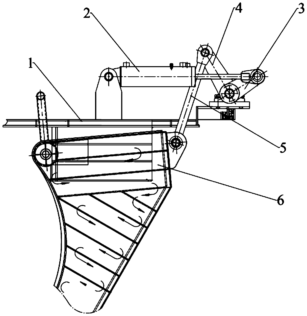
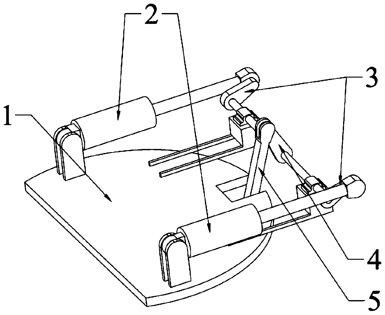
[0039] A hydraulic tilting mechanism for an automatic feeder of a submerged arc furnace, comprising: a support platform 1, a driving mechanism, a rotating shaft, a long rocker arm 4, a connecting rod 5, and a chute 6; wherein, the driving mechanism includes: a hydraulic cylinder 2, a short rocker arm 3;
[0040] The supporting platform 1 is disc-shaped, and the platform can be rotated. combined with Figure 1-3 , the upper surface of the support platform 1 is symmetrically provided with two pairs of lug structures, and is hinged to the installation end of the hydraulic cylinder 2 through a pin shaft, and is preferably designed as follows: the pressure supply device of the hydraulic cylinder 2 is a motor pump, and is equipped with a differential pressure flow measurement Device, hydraulic pressure measuring device is installed in the middle cylinder body of the hydraulic cylinder 2, specifically a flat membrane pressure sensor; two sets of driving mechanisms are arranged on th...
Embodiment 2
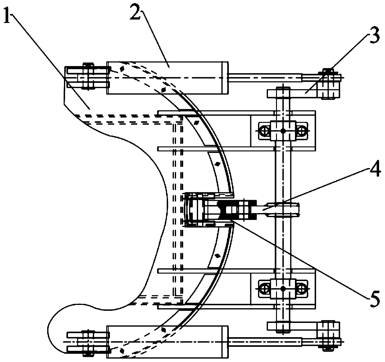
[0048] The difference between this embodiment and embodiment 1 is that, as Figure 4 As shown, there are two groups of long rocker arms 4 and connecting rods 5 parallel and symmetrically distributed on the rotating shaft, wherein the long rocking arms 4 and the rotating shaft are fixed with flat keys, as shown in figure 1 As shown, the upper front end of the chute 6 is hinged with the support platform lower surface fixture, and can rotate around its axis, and its rear end is hinged with two connecting rod 5 ends respectively by the positions on both sides.
[0049] working principle:
[0050] The telescopic movement of the output shaft of the hydraulic cylinder 2 will drive the hinged short rocker arm 3 to swing back and forth. Since the short rocker arm 3 is splined to the rotating shaft, the rotating shaft will drive the long rocking arm 4 to swing back and forth at the same time. The long rocker arm 4 swings, and then drives the connecting rod 5 to generate displacement in...
PUM
 Abstract
Description
Claims
Application Information