Multipoint dynamic measuring device with total temperature and total pressure measuring points arranged back to back

A dynamic measurement and multi-point technology, which is applied in the field of total pressure test and dynamic total temperature of flow field, can solve the problems of small airflow insensitivity angle, inability to measure dynamic total temperature and total pressure, and high experimental cost, so as to improve the spatial resolution of measurement rate and measurement accuracy, increased lifetime and airflow insensitive angular range, and improved spatial resolution

Pending Publication Date: 2020-06-09
BEIHANG UNIV
View PDF0 Cites 4 Cited by
  • Summary
  • Abstract
  • Description
  • Claims
  • Application Information

AI Technical Summary

Problems solved by technology

[0009] The technical problem to be solved by the present invention is: the single-point measurement takes a long time, the cost of the experiment is high, and it is impossible to ensure that the dynamic total temperature and total pressure measurement points are on the same streamline; the existing multi-point measurement device can only realize the dynamic total pressure The measurement of multi-point dynamic total temperature cannot be measured at the same time; the structure of the pressure sensing hole of the existing dynamic pressure measurement device is unreasonable, the total pressure measurement loss is large, the air flow insensitivity angle is small, and the flow separation interferes with the dynamic total pressure measurement; temperature drift Causes errors in total pressure measurement; the existing dynamic temperature and pressure combination probe has a large size and low spatial resolution, and cannot measure the dynamic total temperature and total pressure on the same streamline, causing measurement errors; the dynamic temperature sensor is facing the mainstream , easily damaged, easily affected by oil and dust in the flow field, the airflow insensitivity angle is small, when the pitch angle or deflection angle of the incoming flow to be measured is large, the airflow cannot be fully stagnated, and the surface of the dynamic temperature sensor is hot Insufficient exchange, large total temperature measurement error

Method used


Image

  • Multipoint dynamic measuring device with total temperature and total pressure measuring points arranged back to back
  • Multipoint dynamic measuring device with total temperature and total pressure measuring points arranged back to back
  • Multipoint dynamic measuring device with total temperature and total pressure measuring points arranged back to back

Examples


Embodiment approach

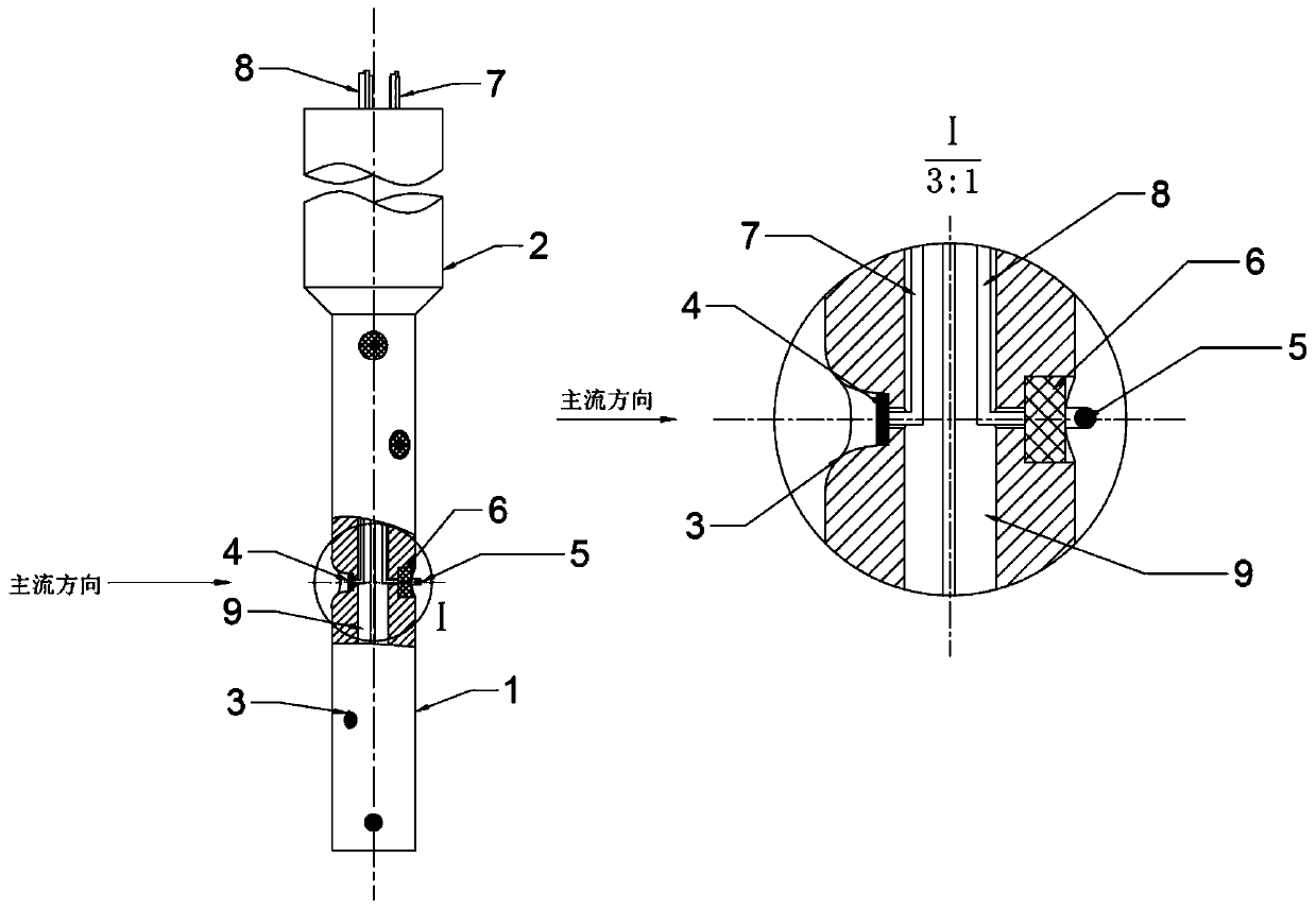
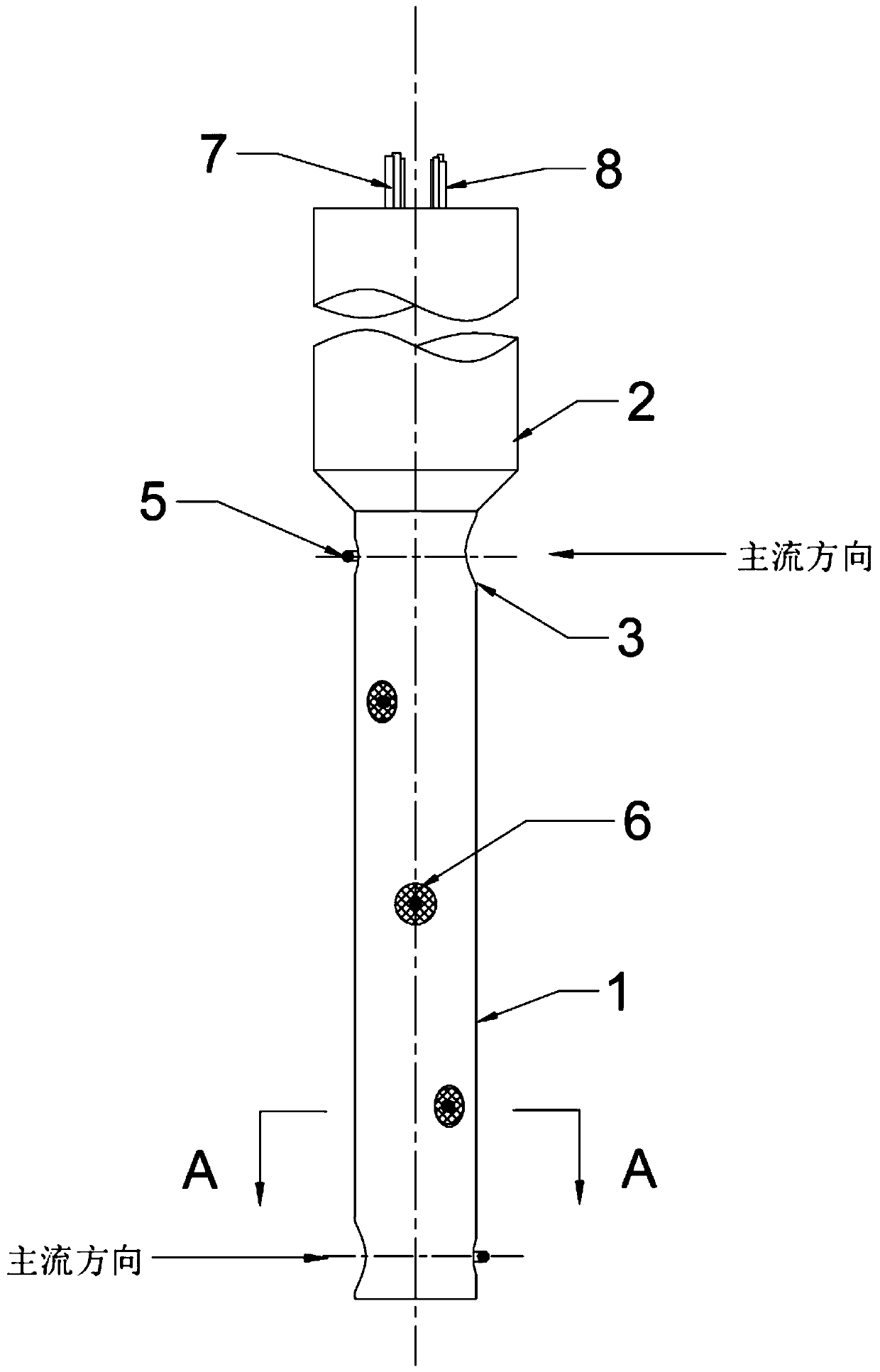
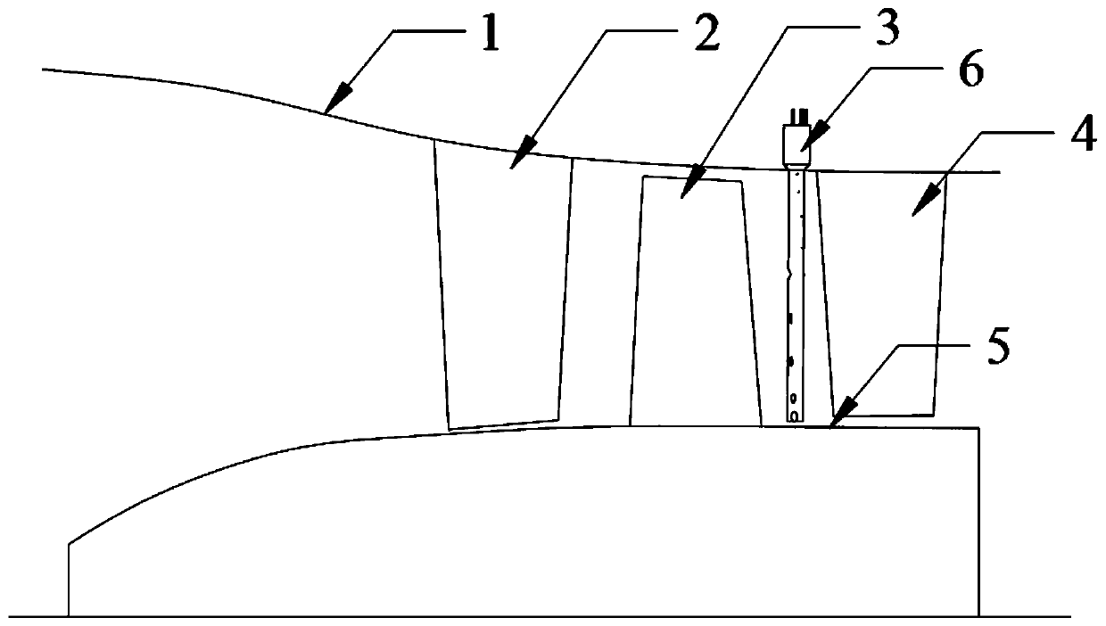
[0037] Such as Figure 1~2 As shown, it is a schematic diagram of a multi-point dynamic measuring device in which the total temperature and total pressure measuring points are arranged in the opposite direction created by the present invention. image 3 is a schematic diagram of the device of the present invention used to measure the flow field between compressor stages, Figure 4 It is a schematic diagram of measuring the boundary layer between compressor stages. This implementation example introduces a multi-point dynamic measuring device with the total temperature and total pressure measuring points facing away from each other. It consists of a head (1), a support rod (2), a pressure sensing hole (3), a dynamic pressure sensor (4), Composed of thermocouple (5), thermal insulation seal (6), dynamic pressure sensor cable (7), dynamic temperature sensor cable (8), lead wire channel (9), characterized in that: the head (1) is a cylinder There are 5 pressure sensing holes (3) ...

Embodiment 2

[0048] For the measurement of total temperature and total pressure distribution along the same blade between turbine stages, the mainstream velocity is relatively high. In order to ensure the strength of the measuring device, a larger lateral dimension of the head of the device and the diameter of the pressure measuring hole should be selected. The temperature sensor can use armored thermal resistance to ensure fine measurement and improve strength. Therefore, the following implementation methods can be adopted:

[0049] Figure 5 It is a structural schematic diagram of the second embodiment of the present invention, Image 6 It is a schematic diagram of the device of the present invention used to measure the flow field between turbine stages. This implementation example introduces a multi-point dynamic measuring device with the total temperature and total pressure measuring points facing away from each other. It consists of a head (1), a support rod (2), a pressure sensing h...


PUM


Abstract

The invention belongs to the technical field of flow field testing, and particularly relates to a multipoint dynamic measuring device with total temperature and total pressure measuring points arranged back to back. The multipoint dynamic measuring device consists of a head part, a support rod, pressure sensing holes, dynamic pressure sensors, a dynamic temperature sensor, a heat insulation sealing element, a dynamic pressure sensor cable, a dynamic temperature sensor cable and a lead channel. The device head part is cylindrical, the pressure sensing holes with a sparse middle part and two dense ends are formed in the surface along the axial direction; the dynamic pressure sensors are packaged in the pressure sensing holes, the pressure sensing holes are designed to be of a micro-loss smooth structure, the center lines of the pressure sensing holes face the predicted incoming flow direction, the dynamic temperature sensors and the pressure sensing holes are distributed back to back, the center lines are collinear, and the dynamic temperature sensors slightly extend out of the head cylindrical surface. Simultaneous measurement of multi-point dynamic total temperature and total pressure of a blade row inlet, a blade row outlet and an interstage flow field in a turbomachinery flow channel can be realized, and the device has the characteristics of large measured airflow insensitiveangle, high measurement precision, high reliability and high spatial resolution.

Description

technical field [0001] The invention belongs to the technical field of flow field dynamic total temperature and total pressure testing, and in particular relates to a multi-point dynamic measuring device with total temperature and total pressure measuring points arranged in the opposite direction, which is suitable for blade row inlets, outlets, and interstages in the flow channel of a turbomachinery. Simultaneous and accurate measurement of multi-point dynamic total temperature and total pressure in the flow field. Background technique [0002] The impeller mechanical devices such as compressors, turbines, pumps, fans, and fans usually need to measure the dynamic total temperature and total pressure at the inlet, outlet, and interstage of the blade row in the flow channel at the same time during the experiment, and the main flow between the blade rows along the blade height The direction changes greatly, and the dynamic total temperature and total pressure also change great...

Claims


Application Information

Patent Timeline
Patent Type & Authority Applications(China)
IPC IPC(8): G01M9/06G01D21/02
CPCG01D21/02G01M9/065
Inventor 马宏伟廖鑫
Owner BEIHANG UNIV
Why Eureka
Try Eureka