Unmanned aerial vehicle inspection system and inspection method

An inspection system and unmanned aerial vehicle technology, applied in the field of inspection, can solve the problems of poor ability of independent judgment, affecting inspection efficiency, and low inspection accuracy

Pending Publication Date: 2020-06-09
GUANGDONG POWER GRID CO LTD +1
View PDF0 Cites 4 Cited by
  • Summary
  • Abstract
  • Description
  • Claims
  • Application Information

AI Technical Summary

Problems solved by technology

[0003] At present, the existing drone inspection system generally needs to deploy base stations along the route to ensure uninterrupted signals, which is very costly and time-consuming. During the flight, the drone only patrols along the GPS coordinates set in advance , its independent judgment ability is poor, the farther the UAV is from the base station, the greater the error, the lower the inspection accuracy, and the take-off and landing of the UAV requires manual assistance, which affects the inspection efficiency

Method used


Image

  • Unmanned aerial vehicle inspection system and inspection method
  • Unmanned aerial vehicle inspection system and inspection method
  • Unmanned aerial vehicle inspection system and inspection method

Examples


Embodiment 1

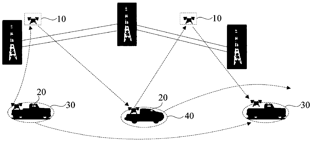
[0043] figure 1 It is a schematic structural diagram of an unmanned aerial vehicle inspection system provided by Embodiment 1 of the present invention. This embodiment can be applied to the field of inspection of poles and towers in the power grid. figure 1 , The drone inspection system includes: the drone 10, a control unit 20, at least one first vehicle-mounted platform 30 and at least one second vehicle-mounted platform 40; wherein the control unit 20 is communicatively connected with the drone 10 for According to the inspection task, the drone 10 is controlled to work, and the image signals collected by the drone 10 are received; the first vehicle-mounted platform 30 is provided with a control unit 20, and the first vehicle-mounted platform 30 is movable and provides for the drone 10 The first platform for the man-machine 10 to lift; the second vehicle-mounted platform 40 is provided with a control unit 20, and the second vehicle-mounted platform 40 is movable and provides th...

Embodiment 2

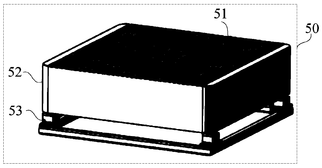
[0047] figure 2 It is a schematic structural diagram of a hangar provided in the second embodiment of the present invention. On the basis of the first embodiment, refer to figure 2 Optionally, both the first vehicle-mounted platform and the second vehicle-mounted platform include a hangar 50 and a mobile vehicle body. The hangar 50 is located on the mobile vehicle body. The drone can land on the hangar 50 and rise in the hangar 50 Up.

[0048] Among them, the UAV 10 rises from the hangar 50 when it starts the inspection task, and after completing the inspection task, it lands to the hangar 50, and the first vehicle platform and the second vehicle platform can be moved by their respective mobile bodies, correspondingly The hangar 50 on the mobile vehicle body can move with the corresponding vehicle-mounted platform to move to the target location to facilitate the take-off and landing of the drone 10.

[0049] Optionally, the hangar 50 is provided with a rolling shutter door 51, a ...

Embodiment 3

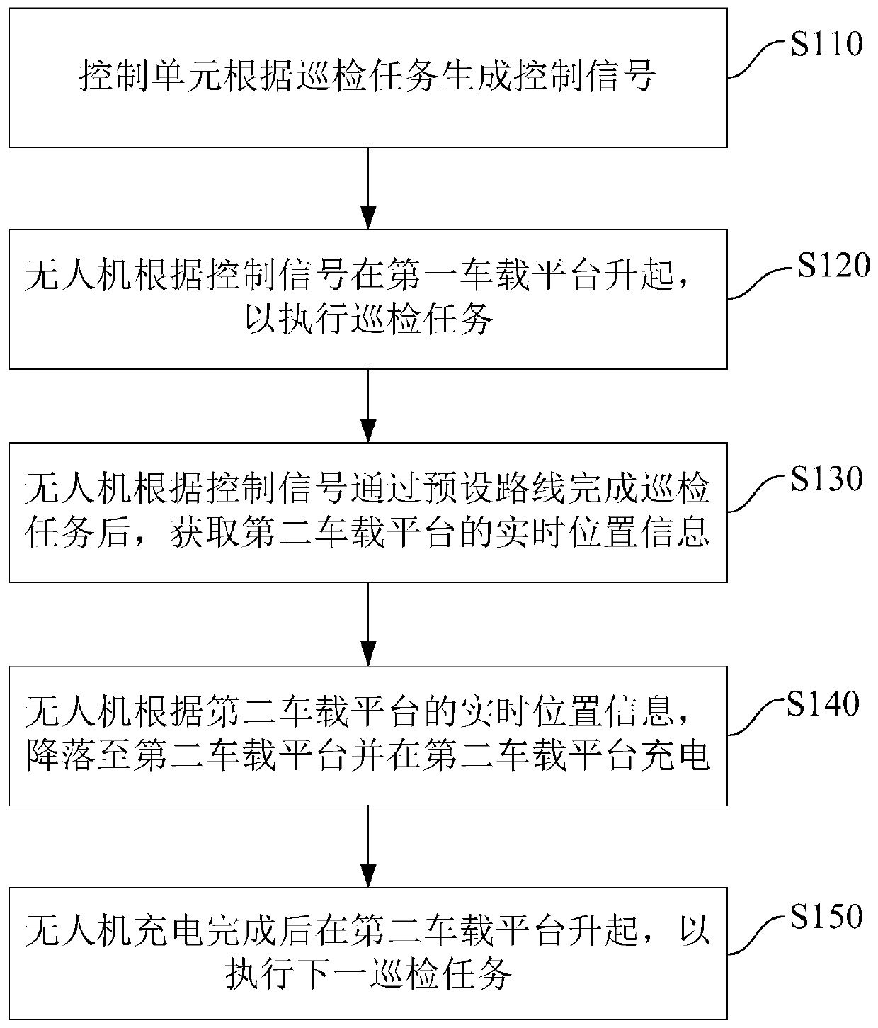
[0059] image 3 It is a flowchart of a drone inspection method provided in the third embodiment of the present invention. The method can be executed by the drone inspection system described in the foregoing embodiment, and specifically includes the following steps:

[0060] Step 110: The control unit generates a control signal according to the inspection task.

[0061] Among them, the control unit can send control instructions to the drone to control the working status of the drone. The inspection task can be an inspection task instruction input to the control unit according to the actual inspection task requirements, and the control signal can be to control the drone. The signal for the drone to perform the inspection task. When the drone is required to inspect the power line, the control unit generates a control signal according to the inspection task and sends the control signal to the drone.

[0062] Step 120: The drone is raised on the first vehicle-mounted platform according to...


PUM


Abstract

The embodiment of the invention discloses an unmanned aerial vehicle inspection system and inspection method. The unmanned aerial vehicle inspection system comprises an unmanned aerial vehicle, a control unit, a first vehicle-mounted platform and a second vehicle-mounted platform. The control unit is in communication connection with the unmanned aerial vehicle and is used for controlling the unmanned aerial vehicle to work according to an inspection task and receiving an image signal acquired by the unmanned aerial vehicle. The first vehicle-mounted platform is provided with a control unit, and the first vehicle-mounted platform is movable and provides a first platform for lifting the unmanned aerial vehicle for the unmanned aerial vehicle. The second vehicle-mounted platform is provided with a control unit, and the second vehicle-mounted platform is movable and provides a second platform for lifting the unmanned aerial vehicle for the unmanned aerial vehicle; wherein the unmanned aerial vehicle can take off from the first vehicle-mounted platform or the second vehicle-mounted platform and can land on the first vehicle-mounted platform or the second vehicle-mounted platform. According to unmanned aerial vehicle inspection system and inspection method provided by embodiment of invention, high real-time precision of the unmanned aerial vehicle in the inspection process can be realized, and meanwhile, manual intervention is not needed for rising and falling of the unmanned aerial vehicle, so that inspection efficiency is improved.

Description

Technical field [0001] The embodiment of the present invention relates to inspection technology, in particular to an unmanned aerial vehicle inspection system and inspection method. Background technique [0002] In the field of power systems at home and abroad, UAVs are used for inspections of power lines of various voltage levels, and pilot inspections of UAVs are carried out on power lines, which greatly improves the efficiency of line inspection operations. Power lines are deployed in multiple provinces. UAV operation teams have carried out routine operations. The development of UAV technology has brought new power inspection methods, and the application effect of UAVs in power line inspection is very significant. [0003] At present, the existing UAV inspection system generally needs to deploy base stations along the line to ensure uninterrupted signals. The cost is very high and time-consuming. The UAV only patrols along the pre-set GPS coordinate points during the flight. , ...

Claims


Application Information

Patent Timeline
Patent Type & Authority Applications(China)
IPC IPC(8): G01N21/88G05D1/10G05D1/12B64C39/02B64D47/08B64F1/00B64F1/02B60P3/11
CPCG01N21/8851G05D1/101G05D1/12G05D1/0005B64C39/024B64D47/08B64F1/00B64F1/02B60P3/11G01N2021/8887B64U10/10B64U2201/00B64U2101/00
Inventor 邱灿树林新宇舒坚梁小强
Owner GUANGDONG POWER GRID CO LTD
Why Eureka
Try Eureka