Fingerprint identification display panel, fingerprint identification method and display device

A fingerprint identification and display panel technology, which is applied in the directions of acquiring/arranging fingerprints/palmprints, character and pattern recognition, printing image collection, etc., can solve the problems of no breakthrough in fingerprint identification and reduce the opening rate, etc., and achieve simple and convenient structure, The effect of improving accuracy

Pending Publication Date: 2020-06-09
BOE TECH GRP CO LTD
View PDF3 Cites 3 Cited by
  • Summary
  • Abstract
  • Description
  • Claims
  • Application Information

AI Technical Summary

Problems solved by technology

[0004] However, the current research on fingerprint identification technology is mainly aimed at the fingerprint technology under the OLED screen. For liquid crystal display (LCD), since it uses a backlight source and a non-self-luminous device, and there is a requirement for the aperture ratio of the liquid crystal display, it is not possible to add components at will to avoid Reduce the aperture ratio, so that the fingerprint recognition under the LCD screen has not been broken through

Method used


Image

  • Fingerprint identification display panel, fingerprint identification method and display device
  • Fingerprint identification display panel, fingerprint identification method and display device
  • Fingerprint identification display panel, fingerprint identification method and display device

Examples


Embodiment 1

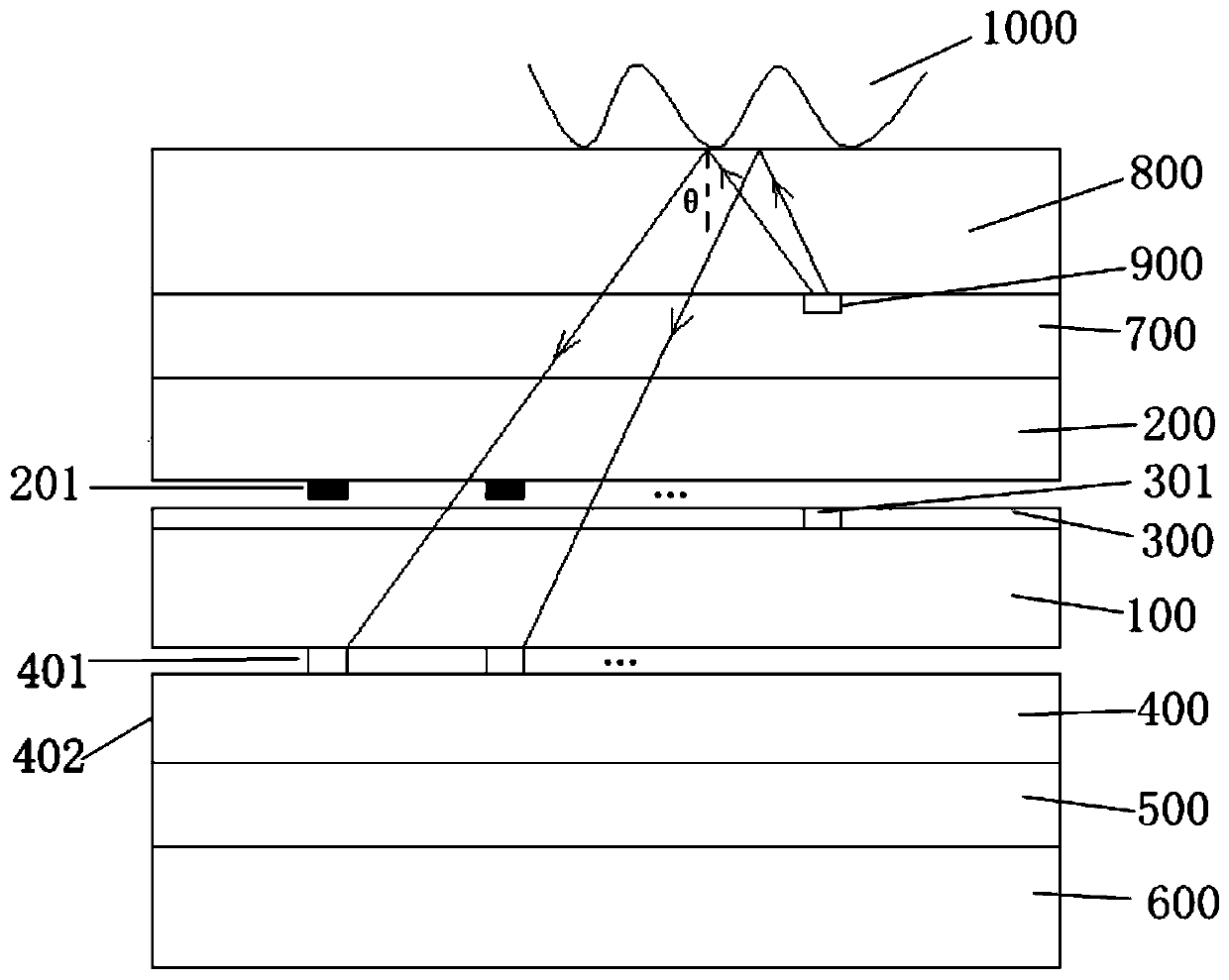
[0061] image 3 It shows the fingerprint recognition display panel according to Embodiment 1 of the present invention, which includes an array substrate 100 and a color filter substrate 200 forming a liquid crystal cell and a liquid crystal layer located in the liquid crystal cell; the color filter substrate 200 is provided with a Black Matrix 201;

[0062] The photosensor layer 400 , the first polarizer 500 and the backlight 600 are sequentially arranged on the array substrate 100 away from the color filter substrate 200 ;

[0063] On the side of the color filter substrate 200 away from the array substrate 100 , the second polarizing plate 700 and the protective layer 800 are stacked in sequence.

[0064] Wherein, the photosensor layer 400 includes a photosensor substrate 402 and a plurality of photosensors 401 and detection circuits disposed on the photosensor substrate 402 . And the position of the photo sensor 401 is opposite to the position of the black matrix 201 in th...

Embodiment 2

[0071] Figure 7 The fingerprint identification display panel of Embodiment 2 of the present invention is shown, most of its structure is the same as that of Embodiment 1, and will not be described again. The difference from Embodiment 1 is that the photosensor layer 400 does not include the photosensor substrate 402, but is directly arranged on the side of the array substrate 100 away from the color filter substrate 200, and the detection circuit is also arranged on the array substrate 100. .

[0072] The cathode of the PIN photosensitive device is close to the surface of the array substrate 100, and the anode is closer to the side of the backlight 600. At this time, in order to facilitate the PIN material to receive the reflected light of the fingerprint, the cathode is made of transparent metal, and in order to avoid the interference of the backlight on the PIN material, the anode For shading metal.

[0073] The working process of fingerprint identification is the same as...


PUM


Abstract

The invention discloses a fingerprint identification display panel, a fingerprint identification method and a display device. The fingerprint recognition display panel comprises a backlight source, afirst polarizing film, an array substrate, a liquid crystal layer, a color film substrate, a second polarizing film and a protective layer which are sequentially arranged in a stacked mode. A black matrix is arranged on the side, facing the array substrate, of the color film substrate. An optical sensor layer is arranged on the side, away from the color film substrate, of the array substrate, theoptical sensor layer comprises a plurality of optical sensors, the optical sensors and the black matrix are arranged in the stacking direction in an aligned mode, and dot patterns are formed by the liquid crystal layer at part of pixel positions and used for forming dot light sources. By adopting the technical scheme, the technical structure is simple, and the recognition precision and accuracy are high.

Description

technical field [0001] The present application relates to the field of display technology, and in particular, to a fingerprint recognition display panel, a fingerprint recognition method and a display device. Background technique [0002] With the progress of modern society, the importance of personal identification and personal information security has gradually attracted people's attention. Due to the uniqueness and invariance of human fingerprints, fingerprint recognition technology has the characteristics of good security, high reliability, and simple and convenient use. Therefore, fingerprint recognition technology is widely used in various fields to protect personal information security, including display fields. Especially in the field of electronic equipment with display functions, such as mobile phones, notebook computers, tablet computers, digital cameras, etc. It is of great significance to enhance the security of electronic equipment and expand its application r...

Claims


Application Information

Patent Timeline
IPC IPC(8): G02F1/1333G02F1/1335G06K9/00
CPCG02F1/13338G02F1/133512G06V40/1318
Inventor 丁小梁王海生刘英明王雷
Owner BOE TECH GRP CO LTD
Why Eureka
Try Eureka