Detection apparatus
A detection device and detection electrode technology, which is applied in the direction of instruments, electrical digital data processing, character and pattern recognition, etc., can solve the problems of data volume expansion, data processing capacity increase, detection time extension, etc.
- Summary
- Abstract
- Description
- Claims
- Application Information
AI Technical Summary
Problems solved by technology
Method used
Image

Examples
Embodiment approach 1
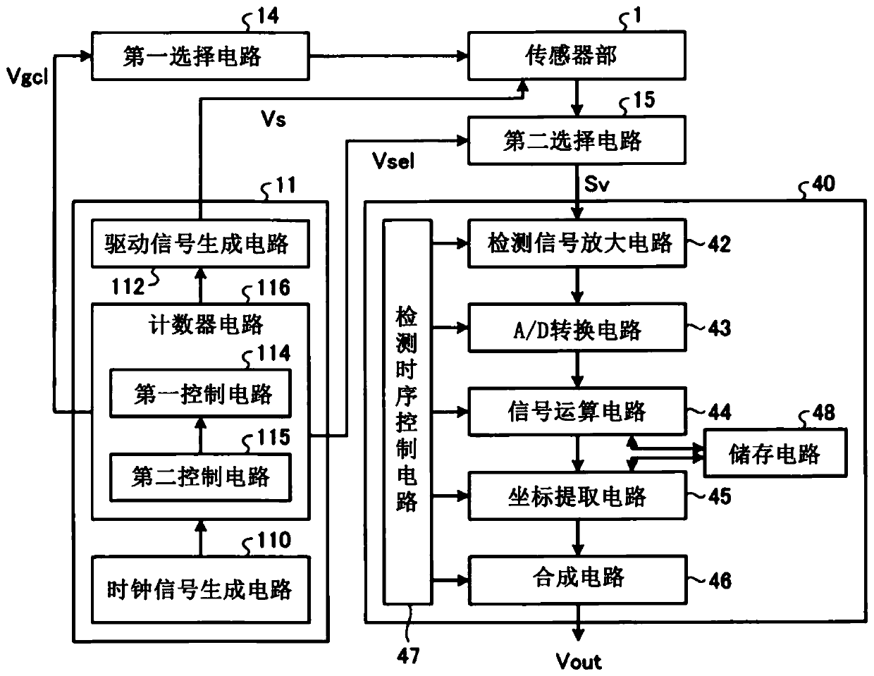
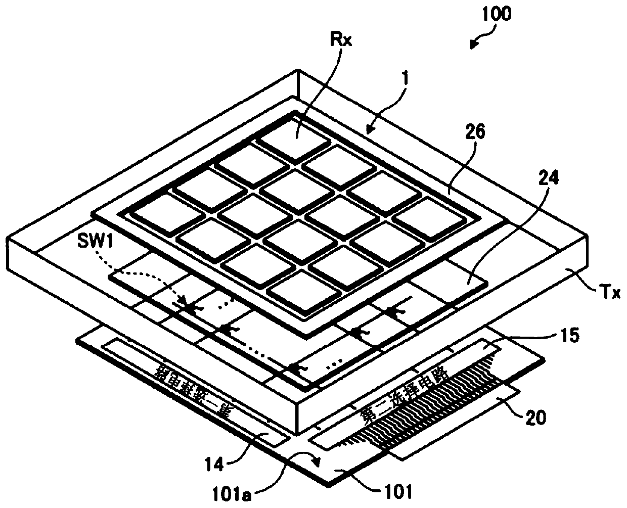
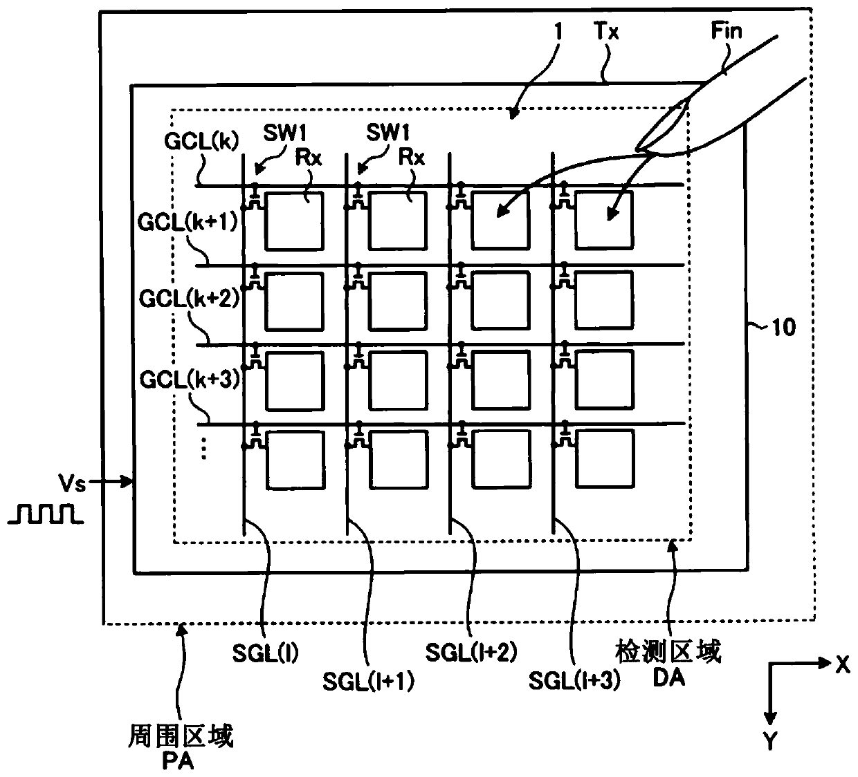
[0040] figure 1 It is a block diagram showing a configuration example of the detection device in the first embodiment. figure 2 It is a schematic diagram showing a configuration example of a detection device. image 3 It is a schematic diagram showing a configuration example of a sensor unit included in the detection device. The detection device 100 of this embodiment is a detection device that detects fine unevenness and capacitance between detection electrodes, for example, a fingerprint detection device. Such as figure 1 As shown, the detection device 100 includes a sensor unit 1 , a detection control circuit 11 , a first selection circuit 14 , a second selection circuit 15 , and a detection circuit 40 .
[0041] Such as figure 2 and image 3 As shown, the sensor unit 1 includes an insulating substrate 101, a plurality of detection electrodes Rx provided on one surface 101a side of the substrate 101, a plurality of switching elements SW1, a scanning line GCL connecte...
Embodiment approach 2
[0145] In Embodiment 1, for the implementation Figure 9 The illustrated case of the positive code selection operation Tdp among the positive code selection operation Tdp and the negative code selection operation Tdm based on a predetermined code has been described, but is not limited thereto. In Embodiment 2, the case where the negative code selection operation Tdm is performed will be described below. It should be noted that the same matters as those in Embodiment Mode 1 will not be described in detail.
[0146] Such as Figure 9 As shown, in the negative code selection operation Tdm, the detection control circuit 11 selects the detection electrode Rx of the first selection object according to the selection signal Vgclm corresponding to the component "-1" of the square matrix Hv. In addition, the detection control circuit 11 selects the detection electrode Rx of the second selection object that is not included in the detection electrode Rx of the first selection object amo...
Embodiment approach 3
[0176] In Embodiment 1 and Embodiment 2, the case where only one of the positive code selection operation Tdp and the negative code selection operation Tdm is performed has been described, but the present invention is not limited thereto. There may be a first mode in which one of Embodiment 1 or Embodiment 2 is executed, and a second mode in which both the positive code selection operation Tdp and the negative code selection operation Tdm are executed. It should be noted that the same description as that of Embodiment 1 and Embodiment 2 will be omitted.
[0177] In the second mode, the first control circuit 114 outputs the selection signal Vgclp and the selection signal Vgclm to the first selection circuit 14, and the first selection circuit 14 selects the detection electrode block RxB according to the selection form of both the selection form Cpp and the selection form Cpm. The included detection electrode Rx is connected to the data line SGL. The second selection circuit co...
PUM
 Abstract
Description
Claims
Application Information
 - R&D
- Intellectual Property
- Life Sciences
- Materials
- Tech Scout
- Unparalleled Data Quality
- Higher Quality Content
- 60% Fewer Hallucinations
Browse by: Latest US Patents, China's latest patents, Technical Efficacy Thesaurus, Application Domain, Technology Topic, Popular Technical Reports.
© 2025 PatSnap. All rights reserved.Legal|Privacy policy|Modern Slavery Act Transparency Statement|Sitemap|About US| Contact US: help@patsnap.com