A permanent magnet synchronous motor temperature control system for new energy vehicles

A permanent magnet synchronous motor, new energy vehicle technology, applied in electromechanical devices, electrical components, electric components and other directions, can solve the problems of reducing the cooling effect of air-conditioning, untimely cooling of the rotor, and limited cooling, so as to achieve accelerated cooling effect, The effect of improving cooling efficiency and improving the utilization rate of cold air

Active Publication Date: 2021-01-29
ZIBO VOCATIONAL INST
View PDF3 Cites 0 Cited by
  • Summary
  • Abstract
  • Description
  • Claims
  • Application Information

AI Technical Summary

Problems solved by technology

However, although this solution uses cold air, the cold air does not cool the rotor at the first time, but the cavity at the end of the rotor. This makes it impossible to use the coldest cold air to cool the rotor immediately, resulting in a delay in cooling the rotor. In addition, This solution will also cause part of the cold air to directly enter the cavity at the right end through the air gap, further reducing the cooling effect of the cold air. In addition, this solution does not effectively distinguish between the parts with the highest temperature rise and the lowest temperature rise in the rotor, and the cooling symmetry is poor. As a result, the temperature of the right end of the motor is higher than that of the left end, which also leads to the limitation of cooling in this solution, and there is a large waste of energy

Method used


Image

  • A permanent magnet synchronous motor temperature control system for new energy vehicles
  • A permanent magnet synchronous motor temperature control system for new energy vehicles
  • A permanent magnet synchronous motor temperature control system for new energy vehicles

Examples


Embodiment 1

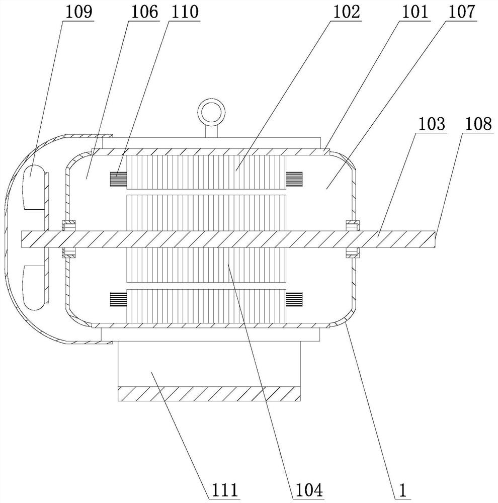
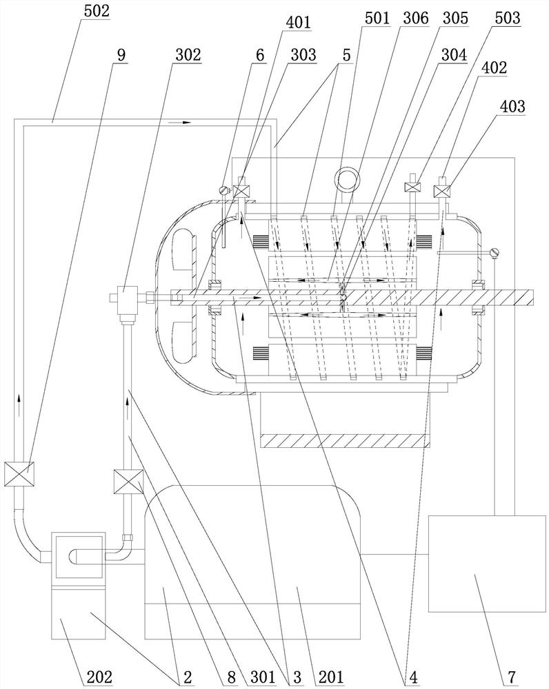
[0037] Such as Figure 1-3 As shown, a permanent magnet synchronous motor temperature control system for new energy vehicles includes a permanent magnet synchronous motor 1, and the permanent magnet synchronous motor 1 includes a casing 101, and a stator 102 is fixed inside the casing 101. A motor shaft 103 is installed in the middle of the casing 101, and a rotor 104 is installed on the motor shaft 103, and a V-shaped radial permanent magnet 105 is embedded in the rotor 104, and the two ends of the rotor 104 are formed with the casing 101. Cavity A106 and cavity B107 are two cavities. The stator core is provided with 24 slots, and windings 110 are provided on the slots. The permanent magnet synchronous motor can adopt a more commonly used 4-pole form, and the motor windings are divided into three phases. 4-pole layout, using single-layer chain winding, energized to generate 4-pole rotating magnetic field, the permanent magnet rotor core is made of silicon steel sheets, which ...

Embodiment 2

[0048] Embodiment 2: the difference between this embodiment and embodiment 1 is:

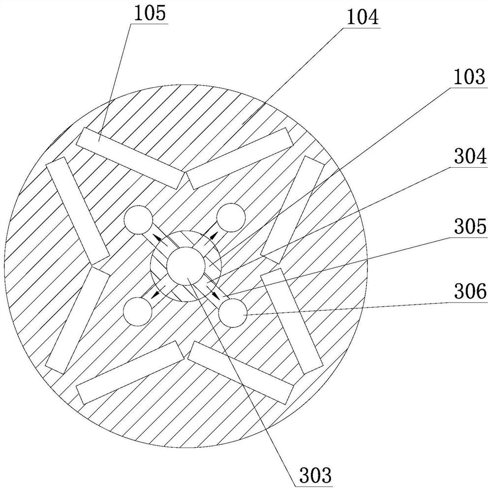
[0049] Such as Figure 4 As shown, at least one radial cold air channel B304 is provided on the motor shaft 103 corresponding to the middle position of the rotor 103, generally two cold air channels B304 are arranged symmetrically, and the middle part of the rotor 103 corresponds to the position of the cold air channel B304. Annular cold air channel E307, the cold air channel B304 communicates with the annular cold air channel E307, and the central part of the rotor 104 is radially provided with a cold air channel C305 that communicates the annular cold air channel E307 with the middle part of the cold air channel D306, where the cold air channel It is only meaningful if the number of D is greater than 2, preferably 3 to 5 times the number of B in the air-conditioning channel. Adopting this structural design can realize cooling air through more cold air passages D306 under the premise of reduci...


PUM


Abstract

The invention relates to a permanent magnet synchronous motor temperature control system for new energy vehicles, which includes a permanent magnet synchronous motor and a cold air supply mechanism. The permanent magnet synchronous motor includes a casing, a stator, a motor shaft and a rotor. Cavity A and cavity B; the cold air intake passage includes a cold air passage A arranged on the motor shaft and a plurality of cold air passages D arranged on the rotor, the cold air passage A communicates with the cold air supply mechanism through a rotary joint and a rubber pipe A, The cold air channel A communicates with the middle of each cold air channel D through multiple radial cold air channels; the cold air exhaust channel includes exhaust channel A and exhaust channel B arranged on the casing, and the exhaust channel A communicates with the cavity , the exhaust passage B communicates with the cavity B, and the exhaust passage A and the exhaust passage B are respectively provided with a gas check valve A. The heat dissipation condition in the motor can be obviously improved, the cooling efficiency is high, the cooling effect is remarkable, and the temperature rise of the motor can be effectively controlled for a long time.

Description

Technical field: [0001] The invention relates to the technical field of motors, in particular to a permanent magnet synchronous motor temperature control system for new energy vehicles. Background technique: [0002] Motor is one of the three core components of new energy vehicles. The drive motors used in existing electric vehicles mainly include DC motors, asynchronous motors, permanent magnet synchronous motors and switched reluctance motors. Due to its wide speed range, high power density, simple process, small size, reliable and durable operation, permanent magnet synchronous motors have developed rapidly in recent years and are widely used in BYD Qin, BYD Song DM, Song EV300 and BAIC EV Series and other new energy vehicles, it has become a mainstream motor and is selected by major new energy vehicle brands. [0003] Although the permanent magnet synchronous motor has many advantages, such as figure 1 Shown is a schematic diagram of the main structure of the existing ...

Claims


Application Information

Patent Timeline
Patent Type & Authority Patents(China)
IPC IPC(8): H02K9/10H02K5/20
CPCH02K5/20H02K9/10
Inventor 孙术华
Owner ZIBO VOCATIONAL INST
Why Eureka
Try Eureka