Eureka AIR delivers breakthrough ideas for toughest innovation challenges, trusted by R&D personnel around the world.

Graded purification waste incineration flue gas treatment equipment

A technology for flue gas treatment and waste incineration, which is applied in the directions of gas treatment, separation methods, and dispersed particle filtration, etc., which can solve the problems of exhaust pipes that are difficult to efficiently cooperate with exhaust flue gas, poor use effect, and difficult to guide drainage, etc., to achieve improved Filtration and purification efficiency, simple structure, and the effect of ensuring purification quality

Inactive Publication Date: 2020-06-12
GUIZHOU UNIV OF ENG SCI
View PDF4 Cites 0 Cited by
  • Summary
  • Abstract
  • Description
  • Claims
  • Application Information

AI Technical Summary

Problems solved by technology

[0002] Waste incineration, waste incineration is the process of reducing the volume of waste through oxidation at high temperature through appropriate thermal decomposition, combustion, melting and other reactions, and becomes residue or molten solid matter. For flue gas treatment equipment, when the flue gas treatment equipment in the prior art is in use, due to the upward flow of flue gas during the incineration process, it is difficult to efficiently guide and discharge the interior, and it is difficult to efficiently cooperate with the exhaust gas to discharge the flue gas. The use effect is poor, so it is necessary to propose a waste incineration flue gas treatment equipment with graded purification to solve the above problems

Method used


Image

  • Graded purification waste incineration flue gas treatment equipment
  • Graded purification waste incineration flue gas treatment equipment
  • Graded purification waste incineration flue gas treatment equipment

Examples


Embodiment Construction

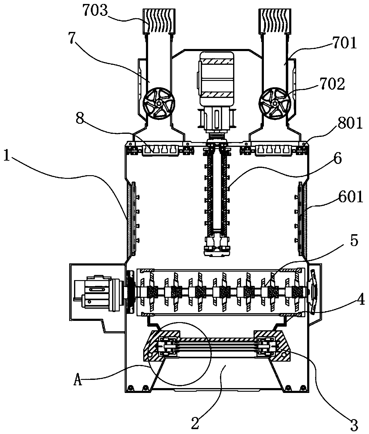
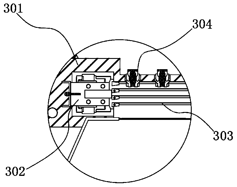
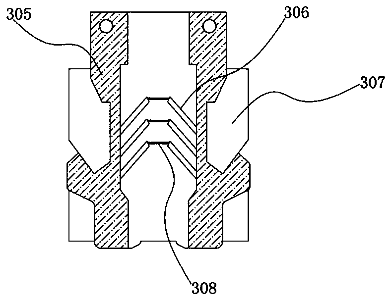
[0019] refer to figure 1 , the present invention provides a technical solution: a waste incineration flue gas treatment equipment with graded purification, which includes a box shell 1, and the inside of the box shell 1 is sequentially provided with a primary filter assembly 3 and an airflow guide assembly from bottom to top 5. The atomization injection assembly 6 and the drainage pipe 7 are characterized in that: the inner side of the bottom end surface of the box shell 1 is provided with a smoke discharge chamber 2, so that the smoke is discharged into the chamber 2 through the opening The exhaust port at the upper end enters the interior and is initially purified by the primary filter assembly 3. The airflow guide assembly 5 acts as a drainage to enhance the fluidity of the internal smoke, so that the smoke flows upward evenly. The airflow guide assembly 5 and the primary filter assembly 3 are also provided with a sleeve 4, the atomization injection assembly 6 atomizes and ...


PUM


Abstract

The invention discloses graded purification waste incineration flue gas treatment equipment which comprises a box body shell, wherein a primary filtering assembly, an airflow guiding assembly, an atomization spraying assembly and a drainage pipeline are sequentially arranged in the box body shell from bottom to top; a flue gas exhaust chamber is arranged in the inner side of the bottom end surfaceof the box body shell so that the flue gas enters the interior through an exhaust port formed in the upper end of the flue gas exhaust chamber, primary purification is carried out through the primaryfiltering assembly, the airflow guide assembly plays a role in drainage and enhances internal flue gas flowability, and flue gas uniformly disperses and flows upwards; a sleeving part is further arranged between the airflow guiding assembly and the primary filtering assembly, the atomization spraying assembly conducts atomization and neutralization treatment on the flue gas to form small-particle-size liquid drops, finally, the purified smoke is discharged through two sets of drainage pipelines, and there are two drainage pipelines which are symmetrically arranged on the left side and the right side of the upper end face of the box shell.

Description

technical field [0001] The invention relates to the technical field of garbage incineration flue gas treatment, in particular to a garbage incineration flue gas treatment equipment for graded purification. Background technique [0002] Waste incineration, waste incineration is the process of reducing the volume of waste through oxidation at high temperature through appropriate thermal decomposition, combustion, melting and other reactions, and becomes residue or molten solid matter. For flue gas treatment equipment, when the flue gas treatment equipment in the prior art is in use, due to the upward flow of flue gas during the incineration process, it is difficult to efficiently guide and discharge the interior, and it is difficult to efficiently cooperate with the exhaust gas to discharge the flue gas. The use effect is poor, so it is necessary to propose a waste incineration flue gas treatment equipment with graded purification to solve the above problems. Contents of the...

Claims


Application Information

Patent Timeline
IPC IPC(8): B01D53/79B01D46/42B01D46/12
CPCB01D53/79B01D46/12B01D46/0089B01D46/0047B01D2258/0291B01D46/64
Inventor 李永湘刘云进罗燏郭才崔吴廷忠杨先稳
Owner GUIZHOU UNIV OF ENG SCI
Why Eureka
Eureka Blog
Learn More